INSTALLATION
3-29
Hardware
and Installation User Manual
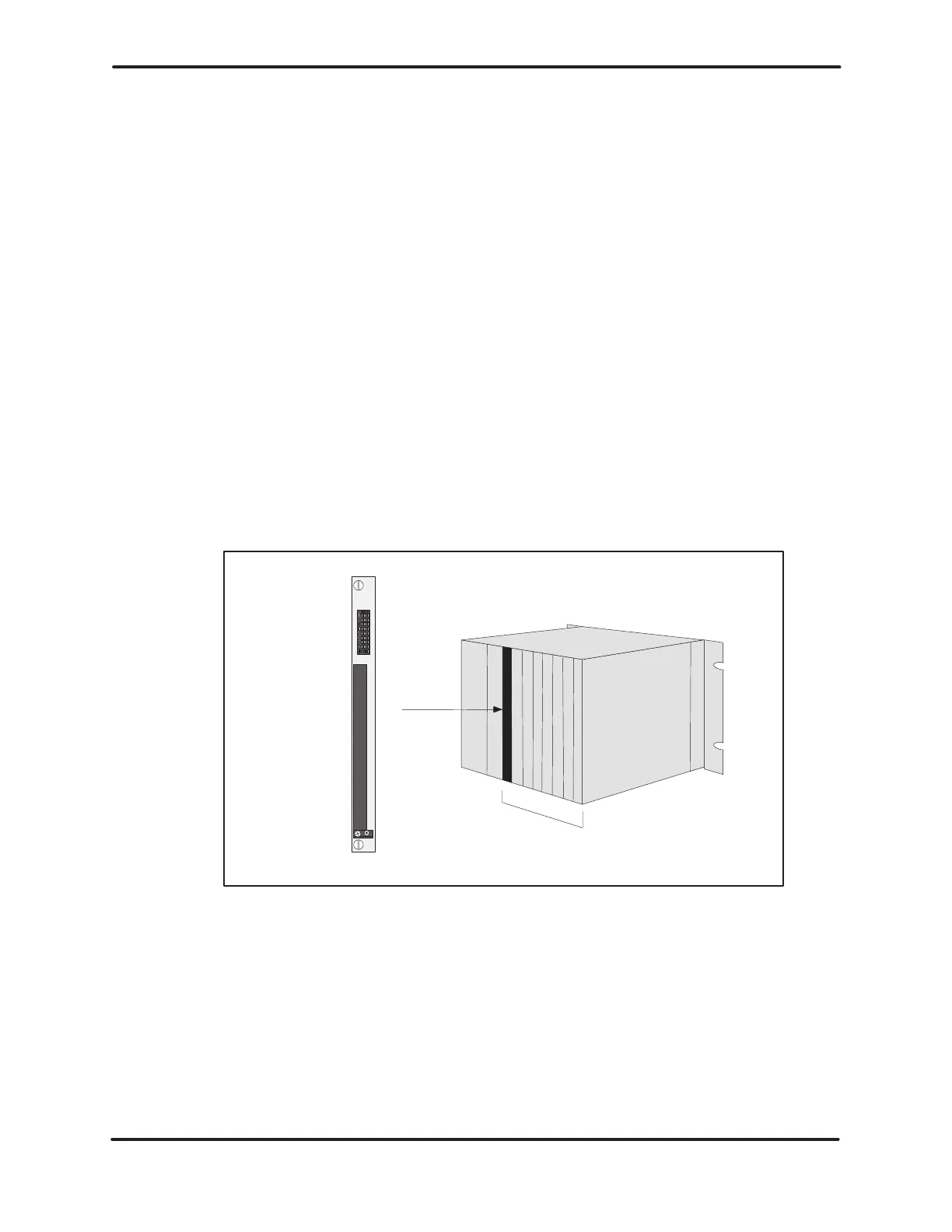
3.6.5 Installing
the I/O Modules
The wiring for the different I/O module terminal blocks may vary. You should
read the user’s manual for an individual module before wiring and installing
the
module. Insert the I/O modules into the base, starting with the slot adjacent
to
the PLC as shown in Figure 3-21.
CAUTION
Use
supply wires suitable for at least
75
C. Signal wiring
connected
in this box must be rated at least 300 V
.
ATTENTION
Employer
des fils d’alimentation pour au moins 75
C.
Le
cablage de signalisation raccorde dans cette boite doit
convenir
pour une tension nominale d’au moins 300 V
.
I/O slots
I/O module
Figure 3-21 Location of I/O Modules in Base
The base power budget is determined from the power provided by the base
power supply and the requirements of the particular modules used. When
determining
the I/O system
layout, take care not to exceed the maximum power
available
from the power supply
.
The total power requirement for all modules drawing power from a Series 505
base
must be less than or equal: 55 W at +5 VDC and 3.75 W at –5 VDC.
Artisan Scientific - Quality Instrumentation ... Guaranteed | (888) 88-SOURCE | www.artisan-scientific.comArtisan Technology Group - Quality Instrumentation ... Guaranteed | (888) 88-SOURCE | www.artisantg.com

 Loading...


