INSTALLATION
3-27
Hardware
and Installation User Manual
3.6.4 Installing
the PLC
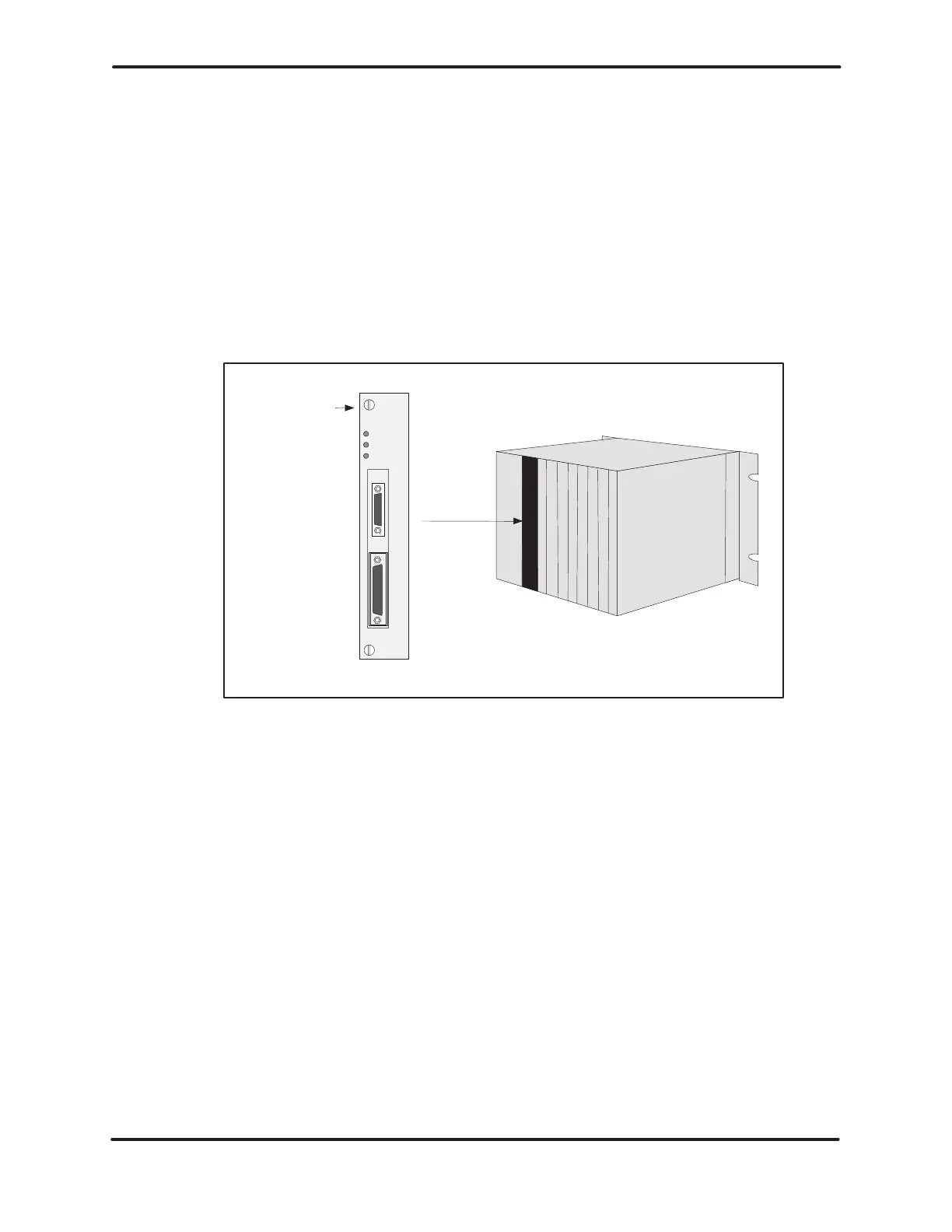
Complete the following steps to install the PLC in the base.
1.
Check dipswitches for correct configuration.
2. Disable all user
-supplied power to the base.
3. Insert
the PLC into its slot adjacent to the power supply as shown in
Figure 3-20.
4. T
ighten the bezel screws.
Bezel screws
Figure 3-20 Location of PLC in Base
5. If you have equipment to connect to the ports, attach the
communication
cables to the appropriate port(s). The RS-232-C/RS-423
compatible port accepts a 25-pin male plug and allows communication
with
equipment up
to 50 ft (15.2 m) away
. The RS-422 compatible port
accepts
a 9-pin male
plug and allows communication up to a distance of
1000 ft
(305 m) for all baud rates supported by the PLC model. Both
ports
are configured as Data T
erminal Equipment (DTE). The pin-outs
are
listed in T
able 3-1.
Artisan Scientific - Quality Instrumentation ... Guaranteed | (888) 88-SOURCE | www.artisan-scientific.comArtisan Technology Group - Quality Instrumentation ... Guaranteed | (888) 88-SOURCE | www.artisantg.com

 Loading...


