Mounting, wiring, connecting, system interfaces, configuration guidelines
12.2 Wiring, connecting
SIMOCODE pro
216 System Manual, 05/2019, A5E40507475002A/RS-AD/004
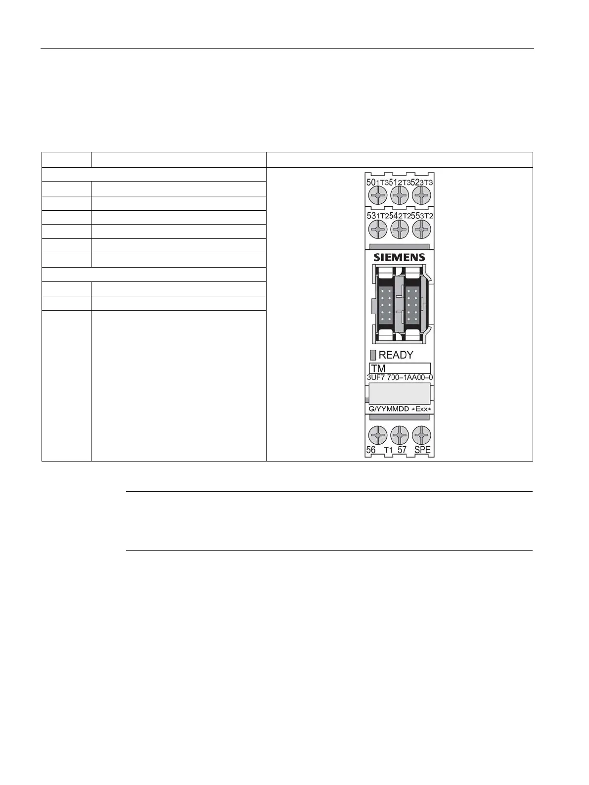
Terminal assignment of the temperature module
The following table shows the assignment of the removable terminals:
Table 12- 15 Pin assignment of the removable terminals of the temperature module
50 Input T3, temperature sensor 1
Input T3, temperature sensor 2
Input T3, temperature sensor 3
Input T2, temperature sensor 1
Input T2, temperature sensor 2
Input T2, temperature sensor 3
Input T1, temperature sensor 1 to 3
Input T1, temperature sensor 1 to 3
SPE
1)
System shielding
1)
pro via terminal SPE with the maximum possible cross-section and
with as short a cable as possible to the functional ground of the control cabinet,
e.g. to the grounded mounting plate of the control cabinet.
You can connect up to three 2-wire or 3-wire temperature sensors.
● 2-wire temperature sensors: Connect a jumper between the T2 terminals and T3
terminals.
● 3-wire temperature sensors: Assign terminals 56 and 57 twice when three sensors are
used.