An overview of system components
SIMOCODE pro
74 System Manual, 05/2019, A5E40507475002A/RS-AD/004
Number that can be connected to
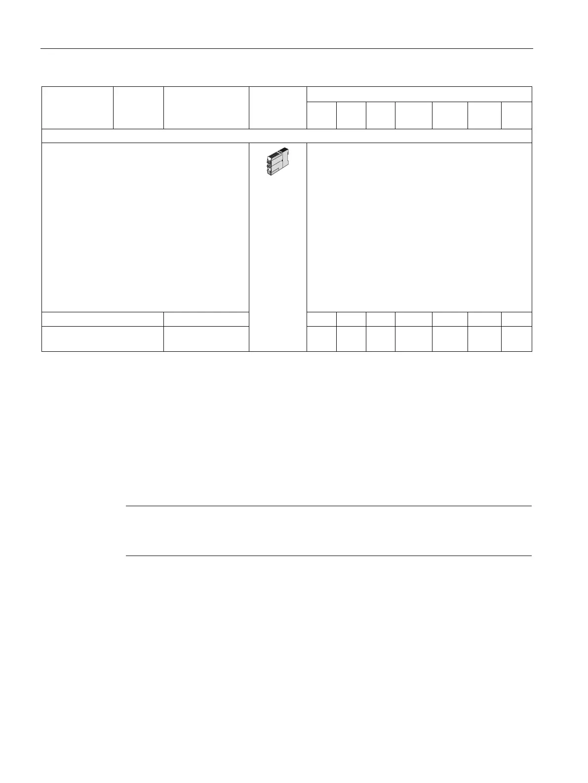
To expand
• the number of inputs and outputs
• the functional scope
the SIMOCODE pro S basic units.
The following inputs and outputs are available:
• 4 digital inputs
• 2 relay outputs
• 1 input for connecting an analog temperature
sensor (sensor types: PT100/PT1000,
KTY83/KTY84 or NTC)
• 1 input for connecting a 3UL23 residual current
transformer
Input voltage 24 V DC 3UF7600-1AB01-0 — 1 — — — — —
Input voltage 110-240 V
3UF7600-1AU00-0 — 1 — — — — —
1) Not needed when using the 2nd generation current/voltage measuring modules (UM+)
Detailed description: See Description of system components (Page 81)
Dimension drawings: See CAx data, dimension drawings (Page 369)
Mounting instructions See Mounting (Page 185)
Configuration information for SIMOCODE pro V PB when using an operator panel with
display and/or a decoupling module: See Chapter Configuration information for
SIMOCODE pro V when using an older basic unit (Page 155) and Configuration notes for
use of a SIMOCODE pro V MR and SIMOCODE pro V EIP basic unit (Page 158).
2)
Note
Use of a DM-F instead of a DM
You can use a fail
-safe digital module (DM-FL or DM-FP) instead of a digital module (DM).
3) Only one temperature sensor can be connected