Alarm, error and system messages
12
12.1 Diagnosis using the LEDs
Each LED can assume various states, such as ON, OFF, flashing. The status of the respective
LED indicates the current status of the device.
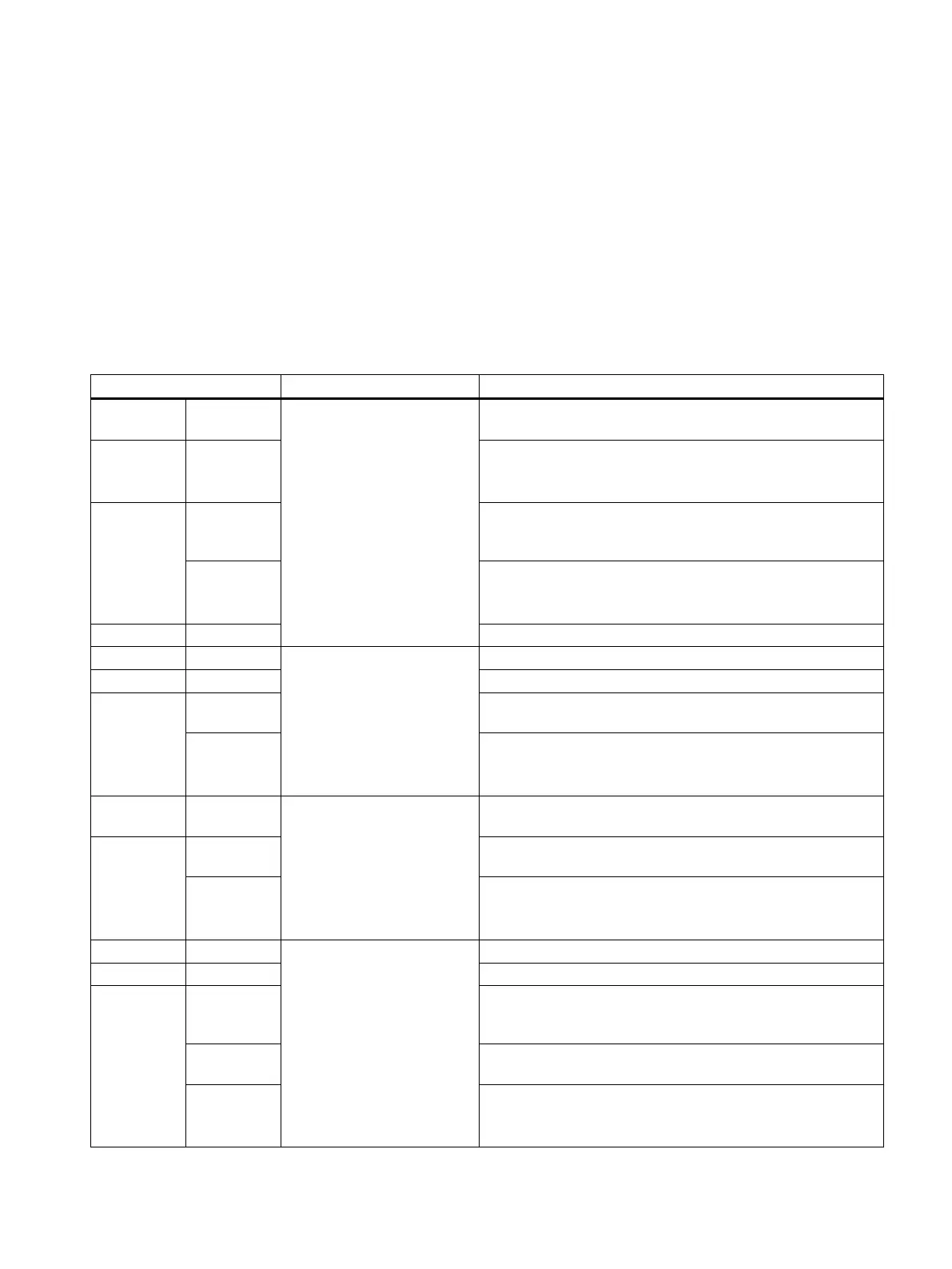
Table 12-1 Diagnostics LEDs of the SIMOTION P320‑4
LED display Meaning Meaning
SF Red System fault This LED indicates that a fault has occurred on SIMO‐
TION P320-4.
LED On An interrupt which can be acknowledged is present (alarm,
message, note).
(See Diagnostics Guide)
LED flashing
0.5 Hz No license exists for technology/optional objects under license.
Licensing must be performed to correct the fault,
see License tab.
5 Hz FAULT state
SIMOTION software does not run in the FAULT state (all LEDs
flash simultaneously).
LED Off SIMOTION P320-4 works error-free.
RUN Green SIMOTION P in RUN mode This LED indicates the state of the user program.
LED On The user program is running.
LED flashing
2 Hz When the RUN operating state is selected, the LED will flash
until the operating state is actually attained.
5 Hz FAULT state
SIMOTION software does not run in the FAULT state (all LEDs
flash simultaneously).
STOPU Yellow SIMOTION P in the STOP
user program
This LED indicates that the technology packages are active.
No user program is being executed.
LED flashing 2 Hz When the STOPU operating state is selected, the LED will
flash until the operating state is actually attained.
5 Hz FAULT state
SIMOTION software does not run in the FAULT state (all LEDs
flash simultaneously).
STOP Yellow SIMOTION P in STOP mode This LED indicates that no user program is running.
LED On The technology packages are not active.
LED flashing
0.5 Hz An overall reset request is indicated by slow flashing,
see Overall reset with the mode selector (on the screen)
(Page 174).
2 Hz When the STOP operating state is selected, the LED will flash
until the operating state is actually attained.
5 Hz FAULT state
SIMOTION software does not run in the FAULT state (all LEDs
flash simultaneously).
SIMOTION P320-4 E / P320-4 S
Commissioning and Hardware Installation Manual, 11/2016 193

 Loading...


