EasyManuals Logo

Siemens SINAMICS Series User Manual

Siemens SINAMICS Series
758 pages
To Next Page IconTo Next Page
To Previous Page IconTo Previous Page
Page #178 background imageLoading...
Page #178 background image
Connecting
6.9 Assignment of terminals and connectors
SINAMICS DCM DC Converter
176 Operating Instructions, 12/2018, A5E34763375A
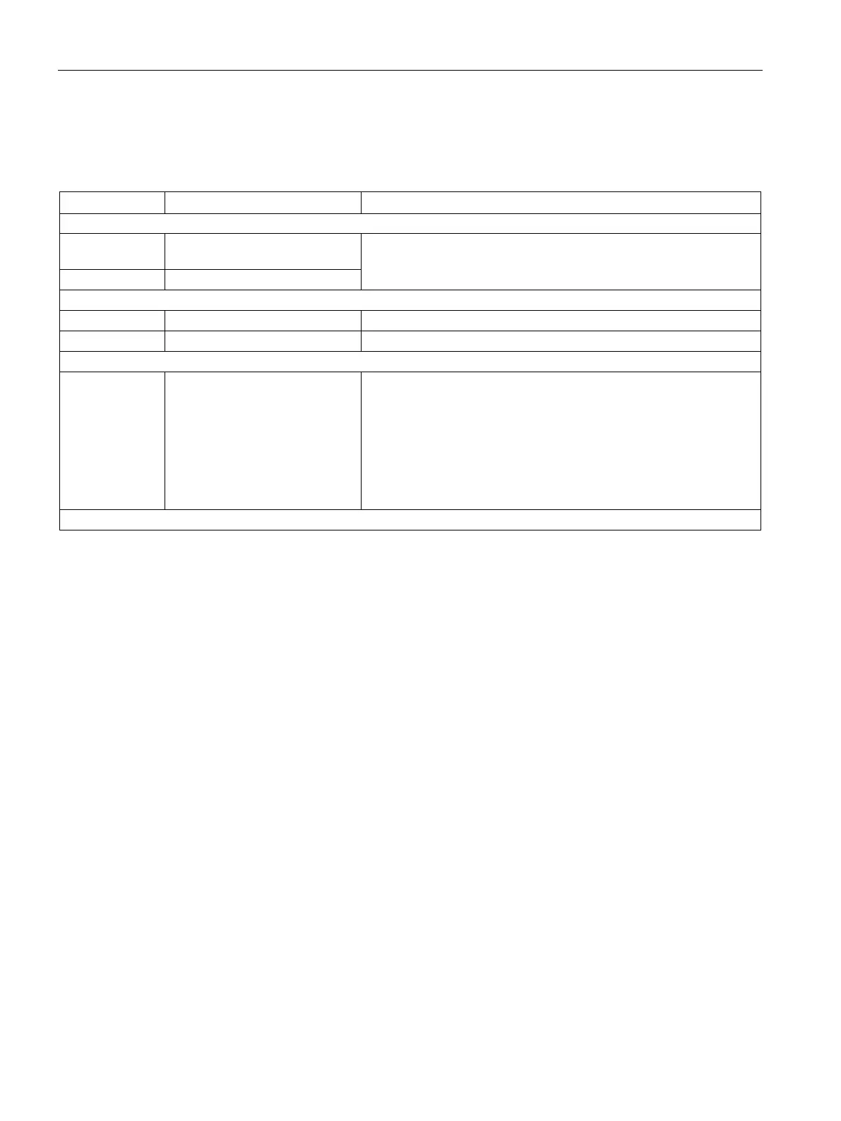
Terminals at the Power Interface (analog tachometer, E-STOP, relay for line contactor)
Table 6- 35 Terminals XR1, XS1, XT1
Terminal
Function
Technical specifications
Analog tachometer
XT1-103 Tachometer connection
8 to 270 V
±270 V
Input resistance 159 kΩ
Resolution ±14 bits
XT1-104
Ground, analog M
Safety shutdown E-STOP
XS1-105
Input (switch)
Ie = 20 mA
XS1-106
Supply (output)
24 V DC, max. load 50 mA, short-circuit proof
Potential-free relay output
XR1-109
XR1-110
Relay for line contactor Current carrying capacity:
≤ AC 250 V, 4 A; cosφ = 1
≤ AC 250 V, 2 A; cosφ = 0.4
≤ DC 30 V, 2 A
External fuse:
max. 4 A / characteristic C recommended
Devices that have option L05 (with "Power interface with DC
electronic power supply") require external protection with max. 6.3 A.
"Power Interface 400 - 600 V" or "Power Interface 690 - 950 V" module

Table of Contents

Other manuals for Siemens SINAMICS Series

Questions and Answers:

Question and Answer IconNeed help?

Do you have a question about the Siemens SINAMICS Series and is the answer not in the manual?

Siemens SINAMICS Series Specifications

General IconGeneral
Product LineSINAMICS
Cooling MethodAir-cooled, Liquid-cooled
Voltage Range200 V to 690 V
Power Range0.12kW - 250kW
Communication InterfacesPROFINET, PROFIBUS, Ethernet
Control ModesVector control, V/f control
Protection ClassIP20
TypeVariable Frequency Drives (VFD)

Related product manuals