Connecting
6.9 Assignment of terminals and connectors
SINAMICS DCM DC Converter
Operating Instructions, 12/2018, A5E34763375A
177
Terminals on the Connector Board
Also refer to "Inputs/Outputs" in the section titled "Descriptions of functions".
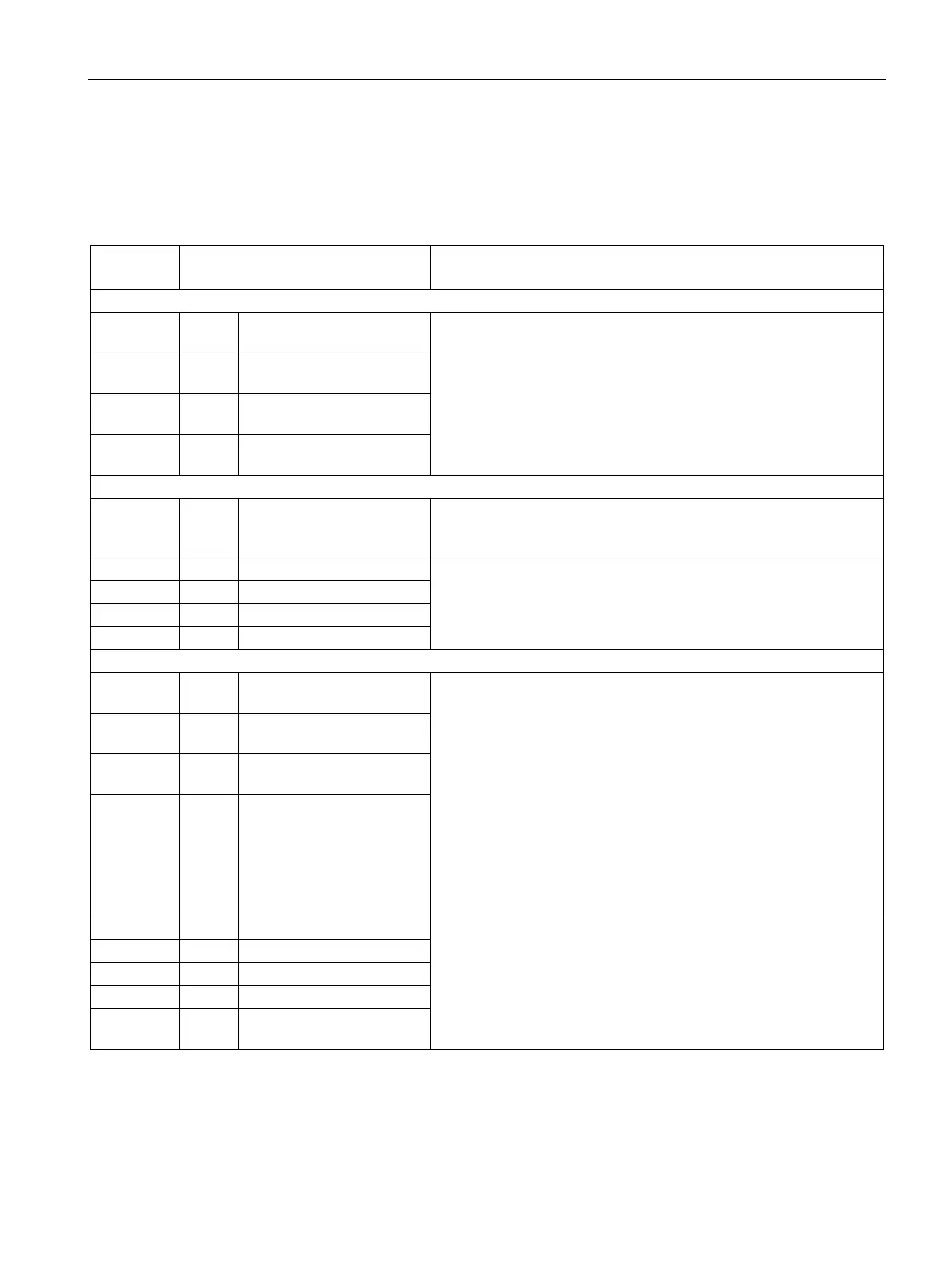
Table 6- 36 Assignment, terminal X177
Analog inputs (assignable inputs)
1
AI 3 +
Analog input 3 Input type (signal type):
Differential input ±10 V; 150 kΩ
Resolution approx. 5.4 mV (±11 bits)
Common-mode controllability: ±15 V
3
AI 4 +
Analog input 4
5
AI 5 +
Analog input 5
7
AI 6 +
Analog input 6
Digital inputs (assignable inputs)
9
10
24 V
DC
24 V supply (output) 24 V DC, short-circuit proof
Max. load 200 mA (terminals 9 and 10 together),
internal supply referred to internal ground
H signal: +15 V to +30 V
L signal: –30 V to +5 V or terminal open
8.5 mA at 24 V
Digital inputs/outputs (assignable inputs/outputs)
15 DI/
Digital input
Type, input/output can be parameterized
Features, inputs:
H signal: +15 V to +30 V
L signal: 0 V to +5 V or terminal open
8.5 mA at 24 V
Features, outputs:
H signal: +20 V to +26 V
L signal: 0 to +2 V
Short-circuit proof; max. current carrying capacity: 100 mA per DO;
max. total load of all DO (CUD left X177:15-22 + CUD right
X177:15-22): 800 mA
Internal protection circuit (freewheeling diode)
If overload occurs: alarm A60018
16 DI/
Digital input
17 DI/
Digital input
18 DI/
DO 7
Digital input
/output 7
H signal: +20 V to +26 V
L signal: 0 to +2 V
Short-circuit proof; max. current carrying capacity: 100 mA per DO;
max. total load of all DO (CUD left X177:15-22 + CUD right X177:15-
22): 800 mA
Internal protection circuit (freewheeling diode)
If overload occurs: alarm A60018
23, 24 M Ground, digital

 Loading...


