Connecting
6.9 Assignment of terminals and connectors
SINAMICS DCM DC Converter
178 Operating Instructions, 12/2018, A5E34763375A
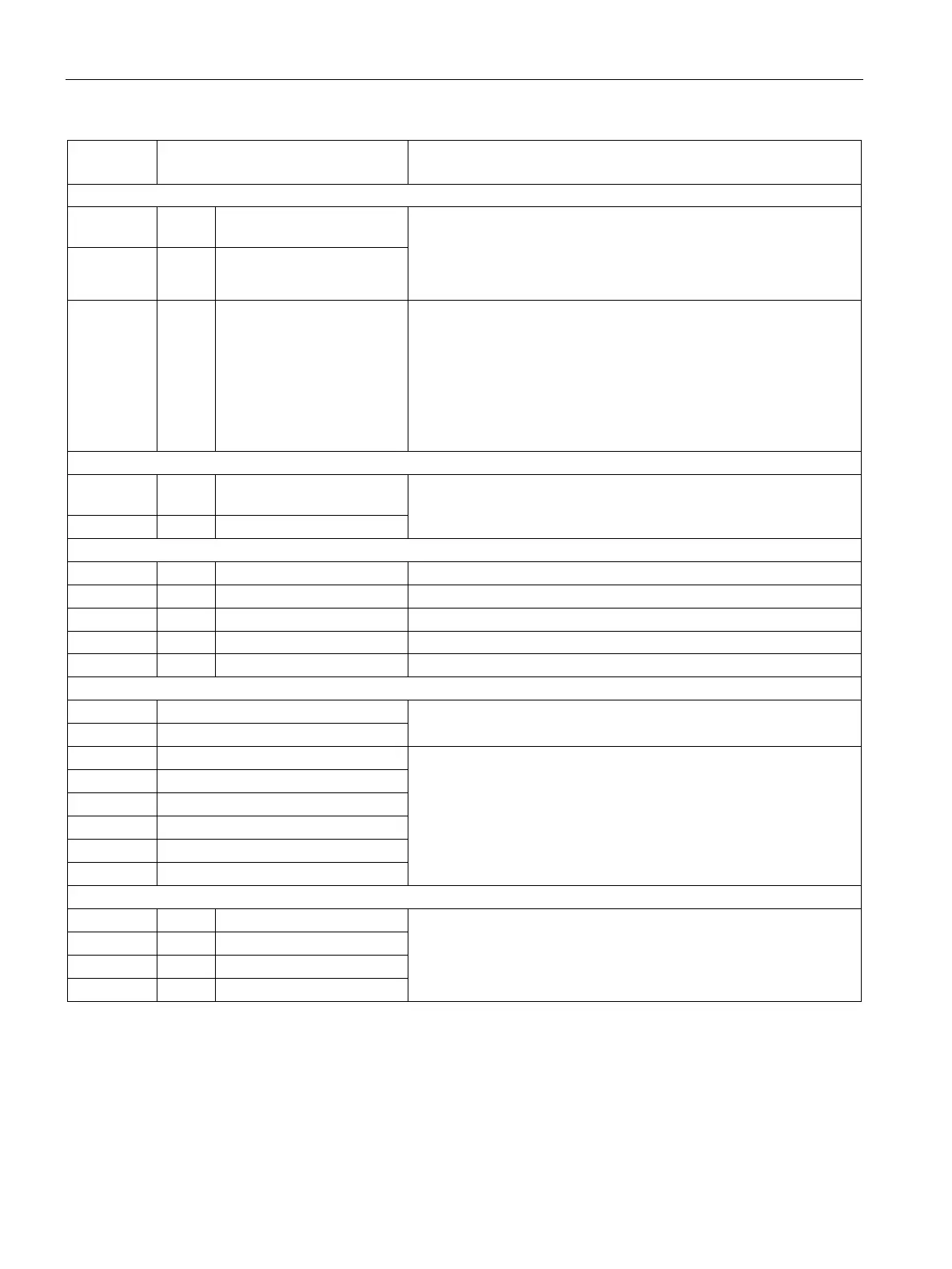
Analog inputs, setpoint inputs (assignable inputs)
25
AI 0 +
Analog input 0
Input type (signal type), parameterizable:
- Differential input ±10 V; 150 kΩ
- Current input 0 - 20 mA; 300 Ω or 4 - 20 mA; 300 Ω
Resolution approx. 0.66 mV (±14 bits)
Common-mode controllability: ±15 V
27
28
AI 1 +
AI 1 -
Analog input 1
29
30
AI 2 +
AI 2 -
Analog input 2 Input type (signal type):
Differential input ±10 V; 150 kΩ
Resolution approx. 0.66 mV (±14 bits)
Common-mode controllability: ±15 V
Note:
An external armature voltage actual value can also be connected at
this input. See function diagram 6902 in the SINAMICS DCM List
31
P10
Reference voltage ±10 V
Tolerance ±1% at 25 °C
Stability 0.1% per 10 °K
10 mA short-circuit proof
Serial interface, peer-to-peer RS485
37 TX+ Send cable + 4-wire send cable, positive differential output
4-wire send cable, negative differential output
4-wire receive cable, positive differential output
4-wire receive cable, negative differential output
Incremental encoder input
Incremental encoder supply
+13.7 to +15.2 V, 300 mA short-circuit proof (electronically protected)
If overload occurs: alarm A60018
42 Ground, incremental encoder
Track 1 positive connection
Load: ≤ 5.25 mA at 15 V (without switching losses)
Pulse duty factor: 1:1
See below for data relating to cables, cable length, shield support,
input pulse levels, hysteresis, track displacement, and pulse
frequency.
Track 1 negative connection
Track 2 positive connection
Track 2 negative connection
Zero mark positive connection
Zero mark negative connection
Analog outputs (assignable outputs)
±10 V, max. 2 mA short-circuit proof, resolution ±15 bits

 Loading...


