Connecting
6.9 Assignment of terminals and connectors
SINAMICS DCM DC Converter
Operating Instructions, 12/2018, A5E34763375A
179
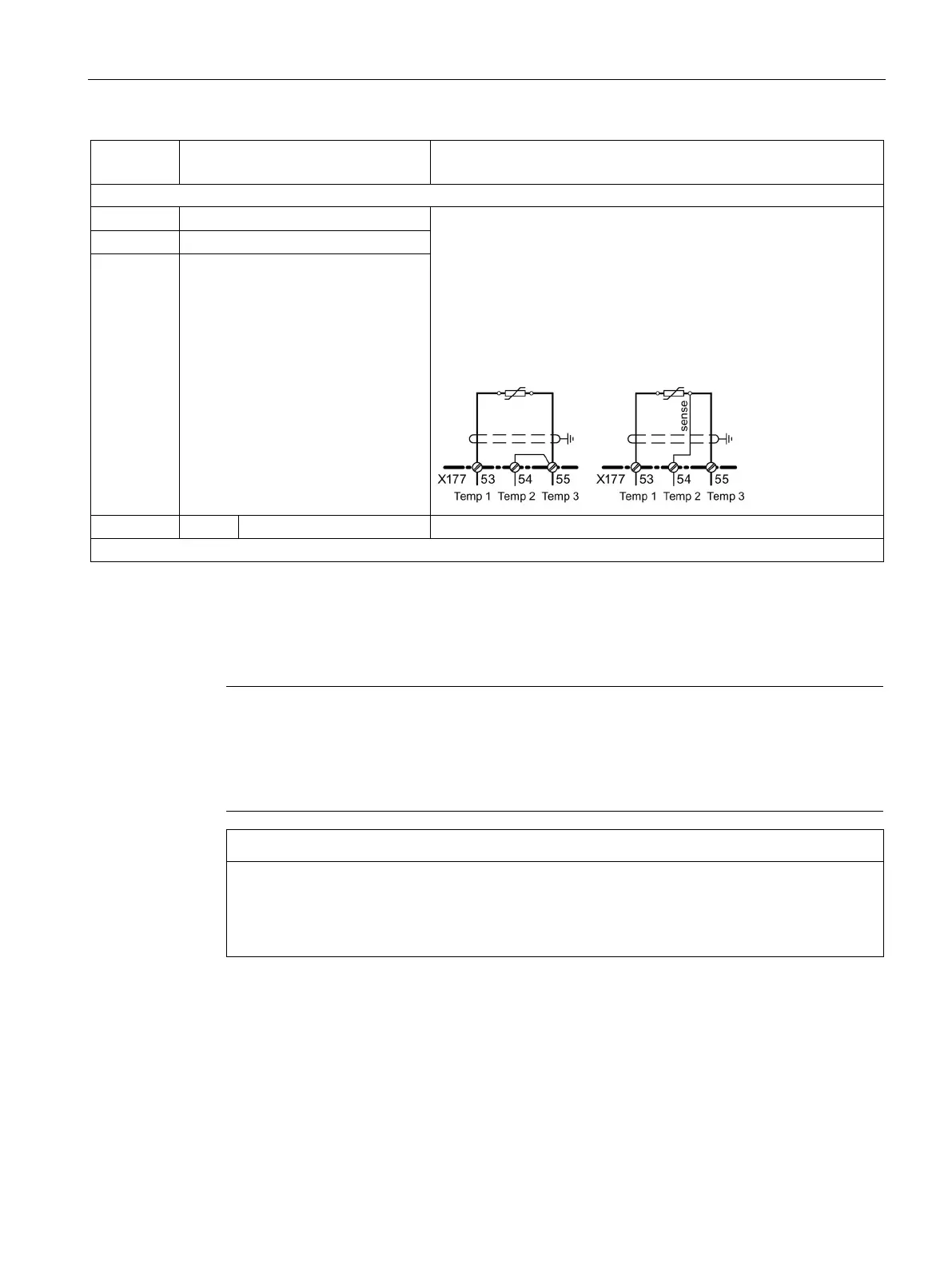
Connections for temperature sensor (motor interface 1)
53 Temp 1 Sensor acc. to p50490 (refer to SINAMICS DCM List Manual)
The cable to the temperature sensor on the motor must be shielded.
The shield is to be connected to ground at both ends.
The cables for the Temp 1 and Temp 3 connections to the
temperature sensor must be approximately the same length.
The sense cable (Temp 2) is used for compensating the cable
resistances. If you are not using a sense cable, terminals 54 and 55
must be connected.
Connection with/without sense cable:
55 Temp 3
Characteristic values for the incremental encoder evaluation electronics
For supported encoder types, refer to the description of parameter p0400 and Appendix A.2
in the SINAMICS DCM List Manual.
Note
Incremental encoder evaluation via terminals X
177.41 to 48 does not support any SSI
-Mounted SMC30 is required for evaluating SSI encoders, see
"Additional system components (Page 191)".
Selecting the encoder type with p0400 does not result in any changes to the supply voltage
for the incremental encoder (terminals X177.41 and 42).
Terminal X177.41 always supplies +15 V. An external power supply is required for
incremental encoders with other supply voltages (e.g. +5 V).

 Loading...


