Connecting
6.9 Assignment of terminals and connectors
SINAMICS DCM DC Converter
180 Operating Instructions, 12/2018, A5E34763375A
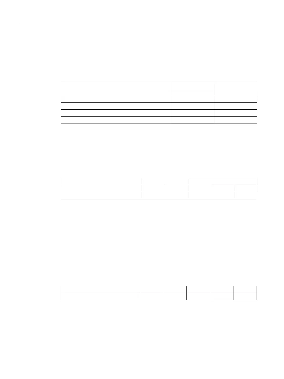
Encoder signals (symmetrical/asymmetrical) up to a maximum of 27 V differential voltage
can be processed by the evaluation electronics.
The encoder type is selected using p0400. The evaluation electronics are adjusted
electronically to the encoder signal voltage:
Low signal level (differential voltage) < 0.8 V < 5.0 V
High signal level (differential voltage)
Hysteresis > 0.2 V > 1.0 V
Common-mode controllability
If the incremental encoder does not supply any symmetrical encoder signals, it must be
grounded with each signal cable twisted in pairs and connected to the negative connections
of track 1, track 2, and zero mark.
The maximum frequency of the encoder pulses is 300 kHz. To ensure the encoder pulses
are evaluated correctly, the minimum distance (Tmin) between two encoder signal edges
(track 1, track 2), as listed in the table, must be adhered to.
1)
2)
Differential voltage at the terminals of the evaluation electronics
The phase error LG (deviation from 90°) that may occur as a result of the encoder and cable can
be calculated on the basis of Tmin:
LG= ± (90° – fp × Tmin × 360°)
LG = phase fault
fp = pulse frequency
Tmin = minimum edge clearance
This formula only applies if the pulse duty factor of the encoder signals is 1:1.
If the incremental encoder is incorrectly matched to the encoder cable, disturbing cable
reflections will occur at the receiving end. To ensure that encoder pulses of this type can be
evaluated without errors, these reflections need to be damped. The limit values listed in the
table below must be adhered to in order to prevent the resulting power losses in the
evaluation electronics adaptor from being exceeded.
3)
Differential voltage of encoder pulses without load (= approximately the supply voltage of the

 Loading...


