Removing a rotary switch
Procedure:
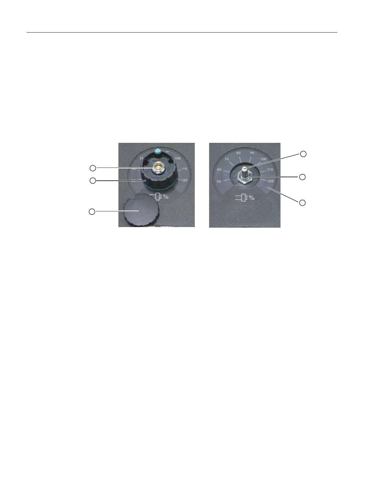
1. Pry off the cap ③ from the knob ② (snap on connection!).
2. Remove the nut of collet ① with a wrench (size 10).
3. Remove the complete knob ②.
4. Remove the lock nut ⑤ on the shaft of the rotary switch ④ with a wrench (size 14).
5. Remove the connector at the end of the rotary switch cable from the socket.
6. Remove the rotary switch.
① Nut of the collet
② Knob
③ Cap
④ Rotary switch shaft
⑤ Fastening nut
⑥ Scale
Figure 4-16 Removing a rotary switch
Installing a rotary switch
Procedure:
1. Push the O-ring ① onto the shaft of the new rotary switch as a seal.
2. Insert the rotary switch into the front cutout so that pressure is applied to the O-ring.
3. Screw the lock nut ④ onto the rotary switch shaft from the front with a wrench (size 14)
(tightening torque: 3 Nm).
4. Connect the arrow ring ③ and knob ⑤.
5. Slide both parts onto the shaft of the rotary switch.
6. Align the arrow point on the ring with position "0" on the scale.
7. Tighten the collet nut of the knob by hand and using a torque wrench tighten to a torque of
2 Nm.
Service cases - hardware
4.5 Machine control panels
Software and hardware
108 Service Manual, 08/2018, 6FC5397-5DP40-6BA1

 Loading...


