8. Place the cap ② on the knob and snap it into position.
9. Fold and fasten the connecting cable ⑦ as shown in the diagram on the right.
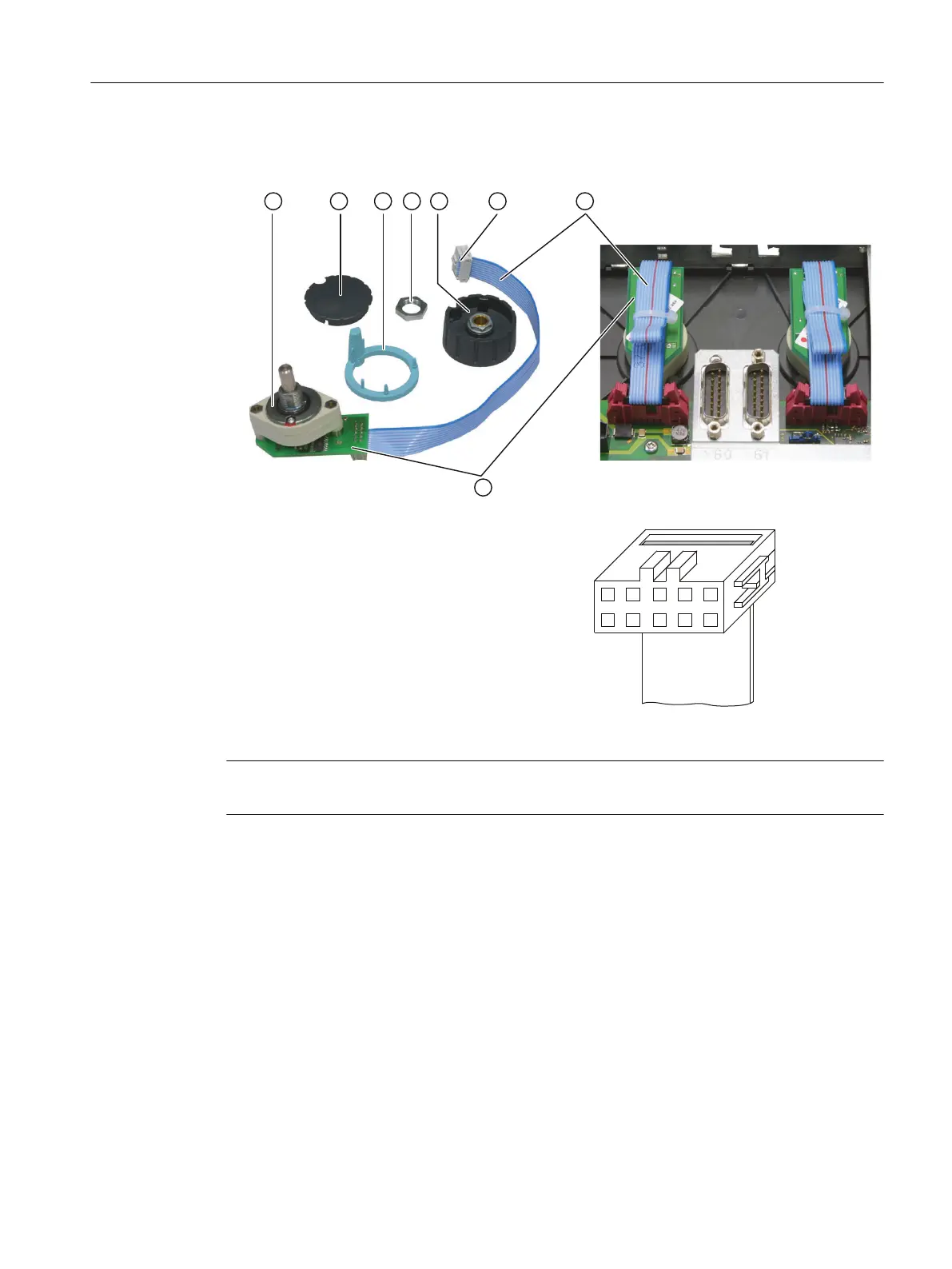
① O-ring Detail diagram of the connector
② Cap
③ Arrow ring
④ Fastening nut
⑤ Knob
⑥ Connection plug
⑦ Connecting cable
⑧ Connection PCB
Figure 4-17 Installing a rotary switch
Note
It is essential that the specified tightening torques are complied with.
Service cases - hardware
4.5 Machine control panels
Software and hardware
Service Manual, 08/2018, 6FC5397-5DP40-6BA1 109

 Loading...


