1
08/2005 Introduction
1.3 O
erator interface
1
♥ Siemens AG, 2005. All rights reserved
SINUMERIK 840D sl Operation/Programming ShopTurn (BAT) – 08/2005 Edition 1-39
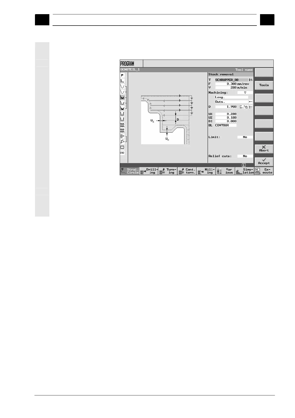
Parameter screen with
help display
The help display in the parameterization screen form explains the
parameters of the machining step individually.
Parameter screen with help display
The colored symbols in the help displays have the following meaning:
Yellow circle = reference point
Red arrow = tool traveling at rapid traverse
Green arrow = tool traveling at machining feedrate

 Loading...


