Overview
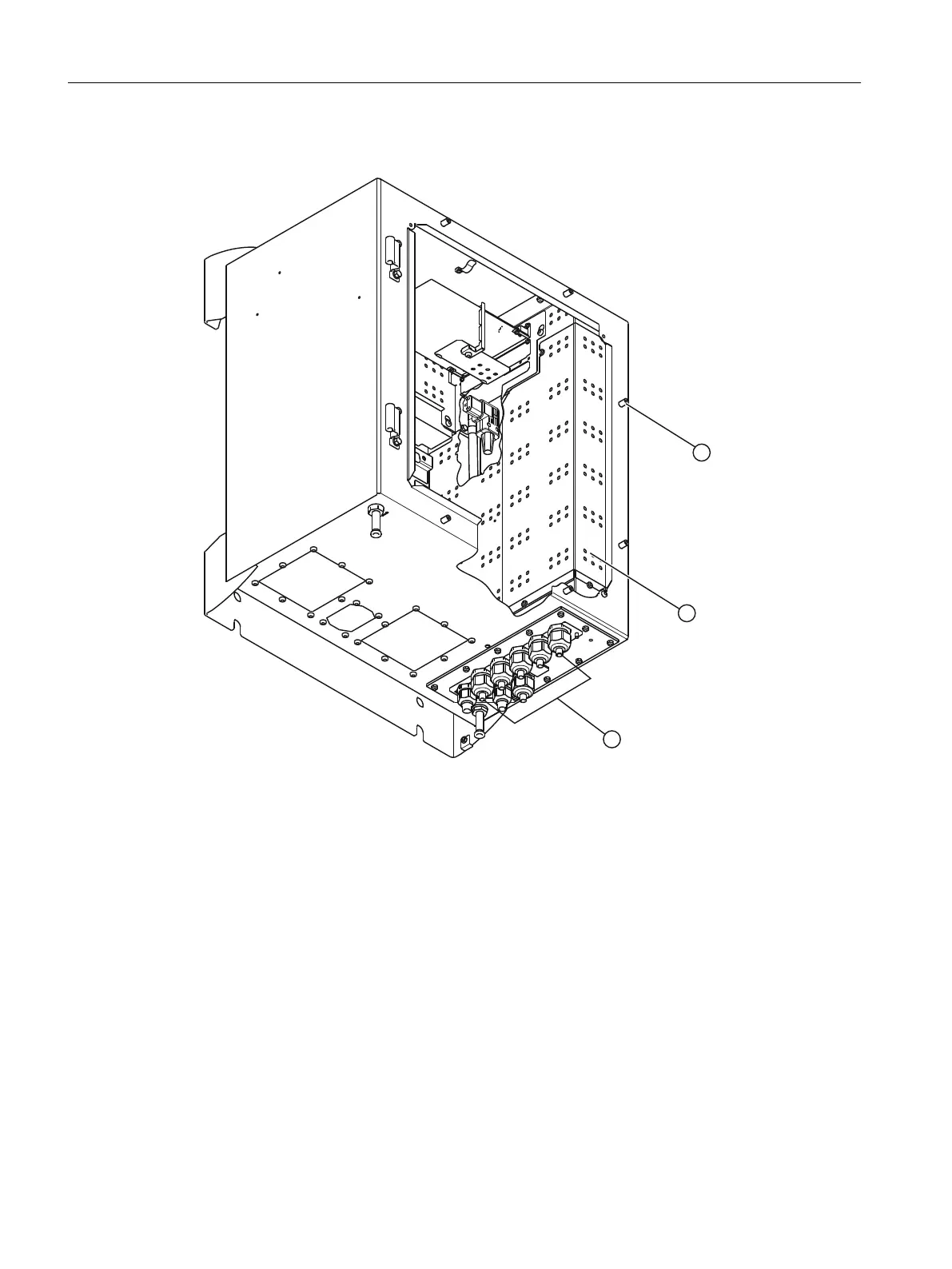
① Door screws
② Shielding plate
③ Cable glands for signal lines (7 units)
Figure8-9 Wall-mounted device, connecting signal cables
Procedure
1. Undo the six screws ① and open the door of the wall-mounted device.
2. Remove the shielding plate ② on the right side panel. To do this loosen the screws.
3. Strip the end of signal cable to a length of approx. 1 cm.
4. Loosen the union nut from the respective cable gland ③ on the underside of the wall-
mounted device.
5. Insert the signal cable through this cable gland ③.
6. Insert the stripped conductors of the signal cable into the terminal block in accordance with
the terminal assignment.
Connecting the device
8.2Electrical connections
Wall-mounted device
108 Operating Instructions, 07/2023, A5E31930403-AB

 Loading...


