4. Loosen the three screws ② and remove the shield plate ①.
5. Loosen the screw ③ on the inside of the right side panel and the eleven hex nuts at the
bottom of the housing.
6. Remove the complete cable gland set.
7. Install the new complete cable gland set ④ with eleven hex nuts with a torque of 0.8Nm.
Note
Fastening the cable glands
Fasten the cable glands (except conduit)
• M16 x 1.5 clamping range 5 to 10 mm made of plastic, counter nut and cap nut (clamp
cables or plugs) with a torque of 3.0Nm.
• M20 x 1.5 clamping range 10 to 14 mm made of plastic, counternut and cap nut with a
torque of 4.5Nm.
• M16x1.5 clamping range 6to10 mm made of metal, counternut and cap nut with a
torque of 6.5Nm.
• M20x1.5 clamping range 10to14 mm made of metal, counternut and cap nut with a
torque of 9.0Nm.
Tightening the cable glands (conduit)
Metal adapter M32x1 on NPT1, tighten the locknut with a torque of 35 Nm. (Connecting
signal cables (Page107))
8. Tighten the screw ③ again with a torque of 2.0Nm.
9. Remount the shield plate. The torque at the screws ② amounts to 0.8Nm.
10.Close the door using six screws.
11.10 Eliminating faults and errors
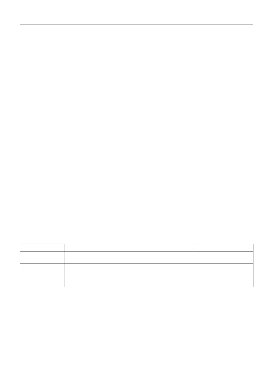
Table 11-1 Error messages
Fault message Description Measures
Invalid device congu‐
ration
No analyzer module was detected. At least one analyzer module is
required to use the device.
Install at least one analyzer
module.
Firmware versions in‐
compatible
The rmware of the basic device and the analyzer modules must be
compatible with one another.
Please contact the service de‐
partment.
Unknown module
type detected
An analyzer module has been detected which is not supported in the
rmware version.
Please contact the service de‐
partment.
Maintenance and servicing
11.10Eliminating faults and errors
Wall-mounted device
154 Operating Instructions, 07/2023, A5E31930403-AB

 Loading...


