7.7.3 Connecting CALOMAT 7
Overview
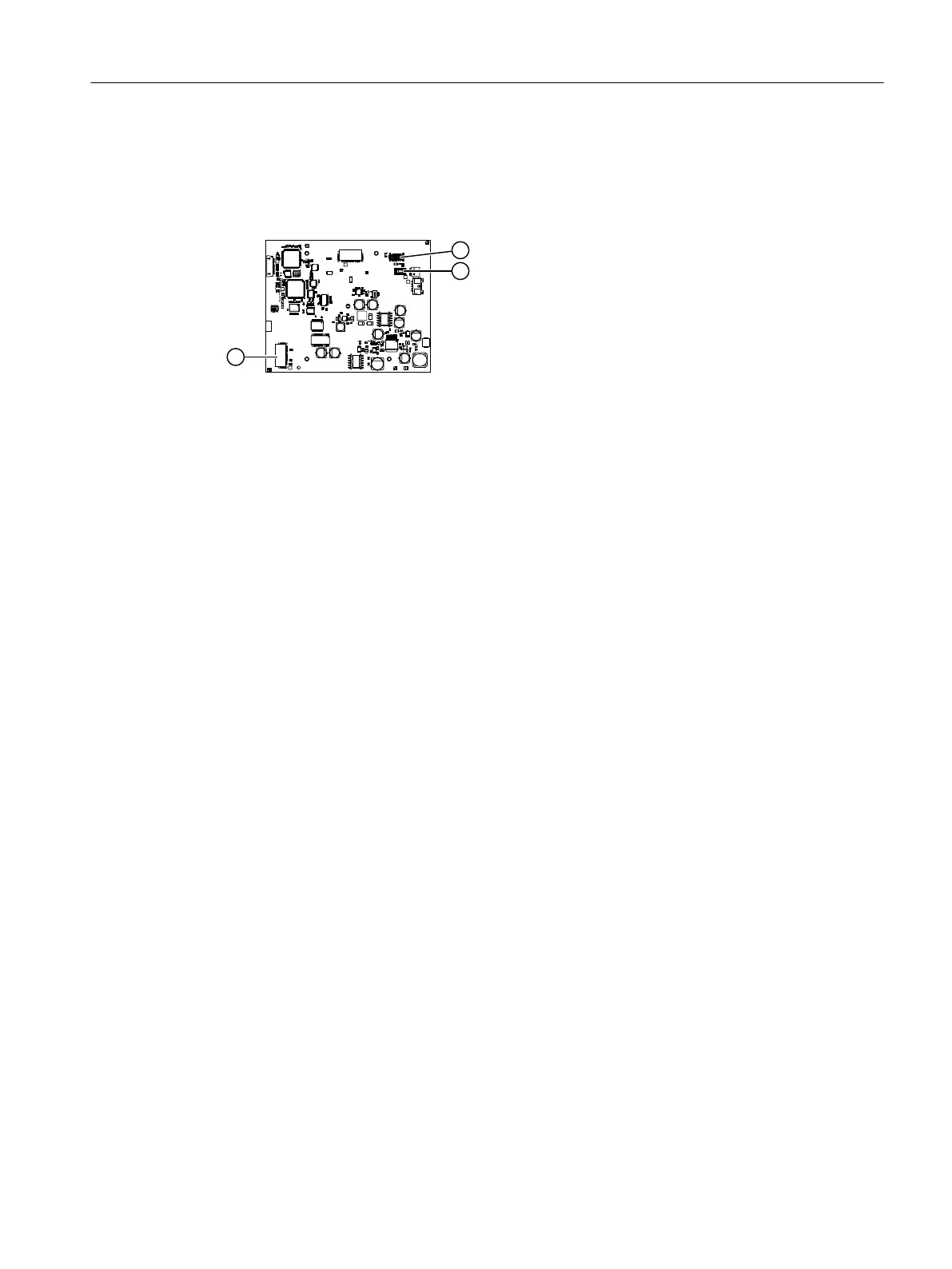
① CAN interface, 12-pin ribbon cable ③ Interface, 26-pin ribbon cable to option mod‐
ule OM 2.1/2.2
② Connector for cable from power supply unit
Figure7-8 AM-FBG interfaces CALOMAT 7
Procedure
1. When an option module OM 2.1 or OM 2.2 is installed:
Connect the option module to the interface ③ of the analyzer module printed circuit board
(AM-FBG) using the existing 26-pin ribbon cable.
2. Connect the processing unit (PU) to the CAN interface ① on the analyzer module printed
circuit board (AM-FBG) using the existing 12-pin ribbon cable.
3. Ensure that power is provided to the analyzer module printed circuit board from the power
supply unit ② via the power cable, see Connecting the power supply (Page113).
4. Connect the gas connections, see CALOMAT 7 (Page100).
5. Check the gas paths for leaks, see Checking gas paths for leaks (Page133).
6. Close the housing door using the six screws.
Tighten the screws on the door with a torque of 3.5Nm.
Installing / removing and connecting analyzer and option modules
7.7Connecting analyzer modules
Wall-mounted device
Operating Instructions, 07/2023, A5E31930403-AB 75

 Loading...


