9.6.2 Recommended test setup for analyzer modules in standard version
Arrangement of the gas connections in analyzer modules in standard version
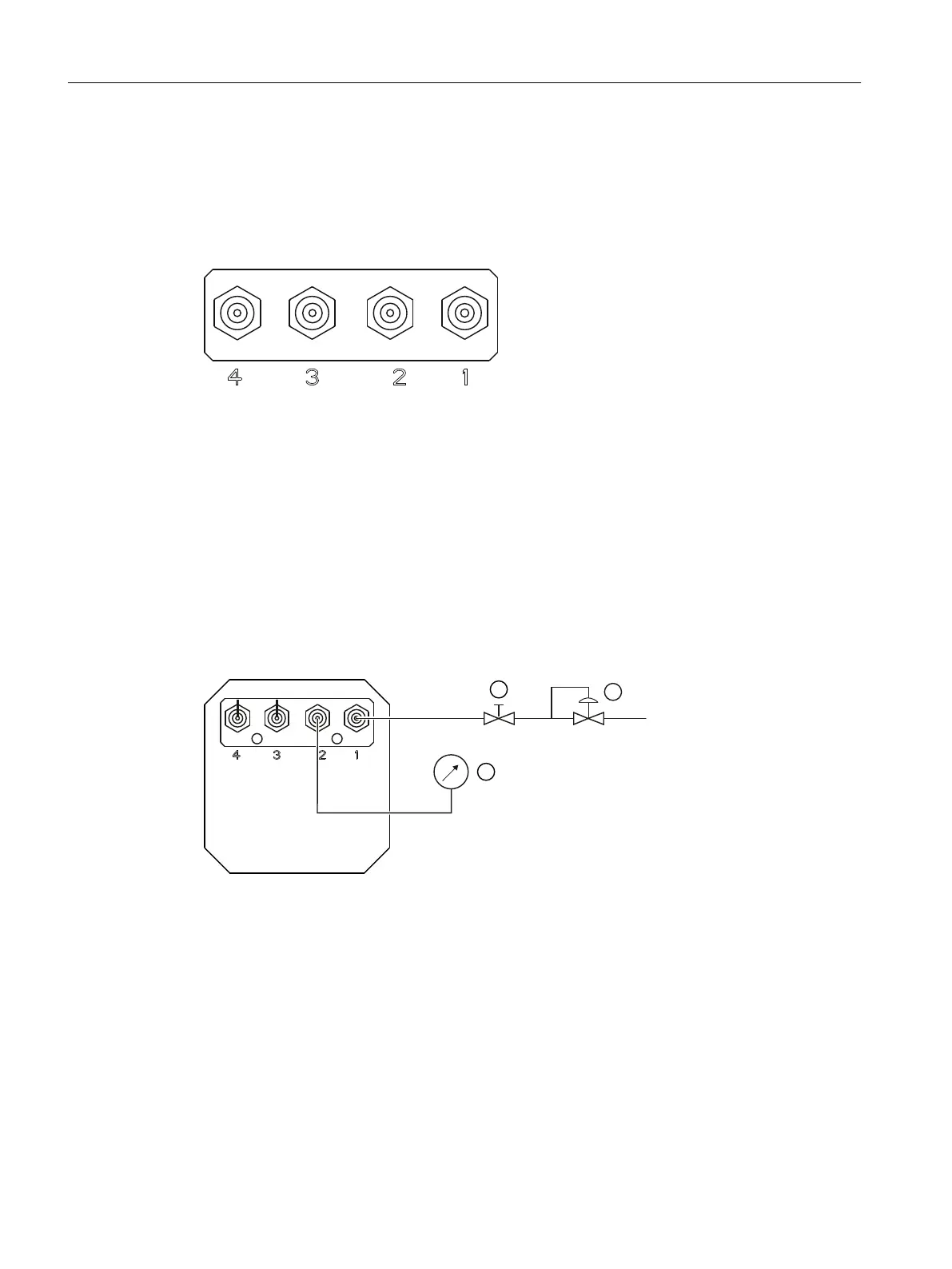
The gure below is a schematic view of the gas connections:
1 Sample gas inlet
2 Sample gas outlet
3 ULTRAMAT 7: Reference gas outlet
OXYMAT 7 (high-pressure version) / CALOMAT 7: Not assigned, dummy plug
OXYMAT 7 (low-pressure version): Bypass outlet
4 OXYMAT 7 / ULTRAMAT 7: Reference gas inlet
CALOMAT 7: Not assigned, dummy plug
Figure9-1 Arrangement of the gas connections
Test setup for leakage test of analyzer modules in standard version
To check for leaks, we recommend the test setup shown below:
① Shut-o valve
② Pressure regulator
③ Manometer (gauge pressure)
1 Sample gas inlet
2 Sample gas outlet
3 OXYMAT 7 / ULTRAMAT 7: Unscrewing blanking plugs
4 OXYMAT 7 / ULTRAMAT 7: Unscrewing blanking plugs
Figure9-2 Recommended test setup to check for leaks
Commissioning
9.6Checking gas paths for leaks
Wall-mounted device
134 Operating Instructions, 07/2023, A5E31930403-AB

 Loading...


