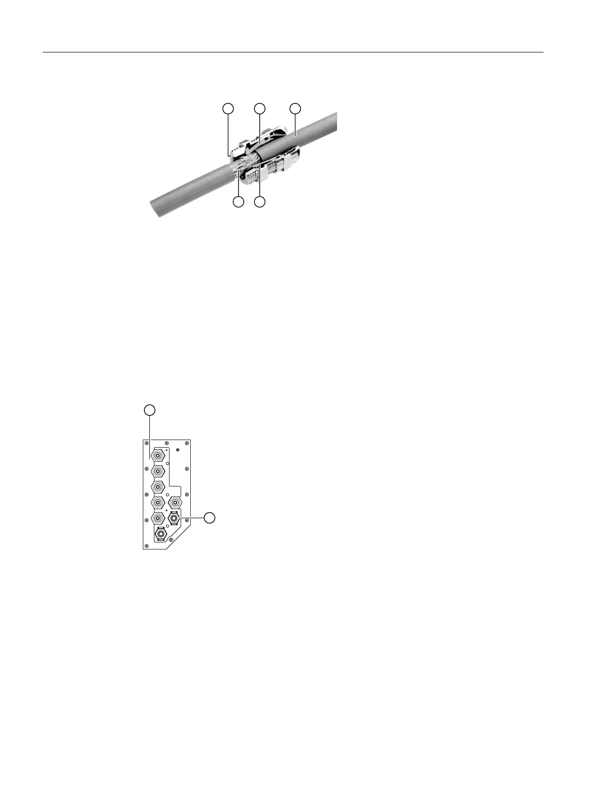
1. Prepare the Ethernet cable:
① Cable gland
②④ Contact shielding
③ Ethernet cable
⑤ Shielding braid
Figure8-10 Ethernet cable shielding
– Isolate the Ethernet cable ③ at the desired location so that the braid ⑤ is exposed over
a length of approx. 1 cm.
– Insert the Ethernet cable through the cable gland. Make sure that the exposed shielding
braid rests on the shield contact ② or ④.
– Screw the cable gland closed.
2. Fasten the prepared gland at the device:
⑥ Plate with cable glands
⑦ Position cable gland Ethernet cable (underside of the device)
Figure8-11 Ethernet cable: Position of the cable gland
– Fasten the Ethernet cable in the cable gland ⑦ at the plate ⑥.
Connecting the Ethernet cable
1. Isolate the free cable end.
2. Assemble the stripped cores in a FastConnect plug.
3. Insert the Ethernet plug into the service interface of the processing module. You must feel for
the position of the interface.
Connecting the device
8.2Electrical connections
Wall-mounted device
112 Operating Instructions, 07/2023, A5E31930403-AB

 Loading...


