9ถPD[
5
&
,
/
5
/
0
'2
'2
'2
'2
'2
'2
*1'
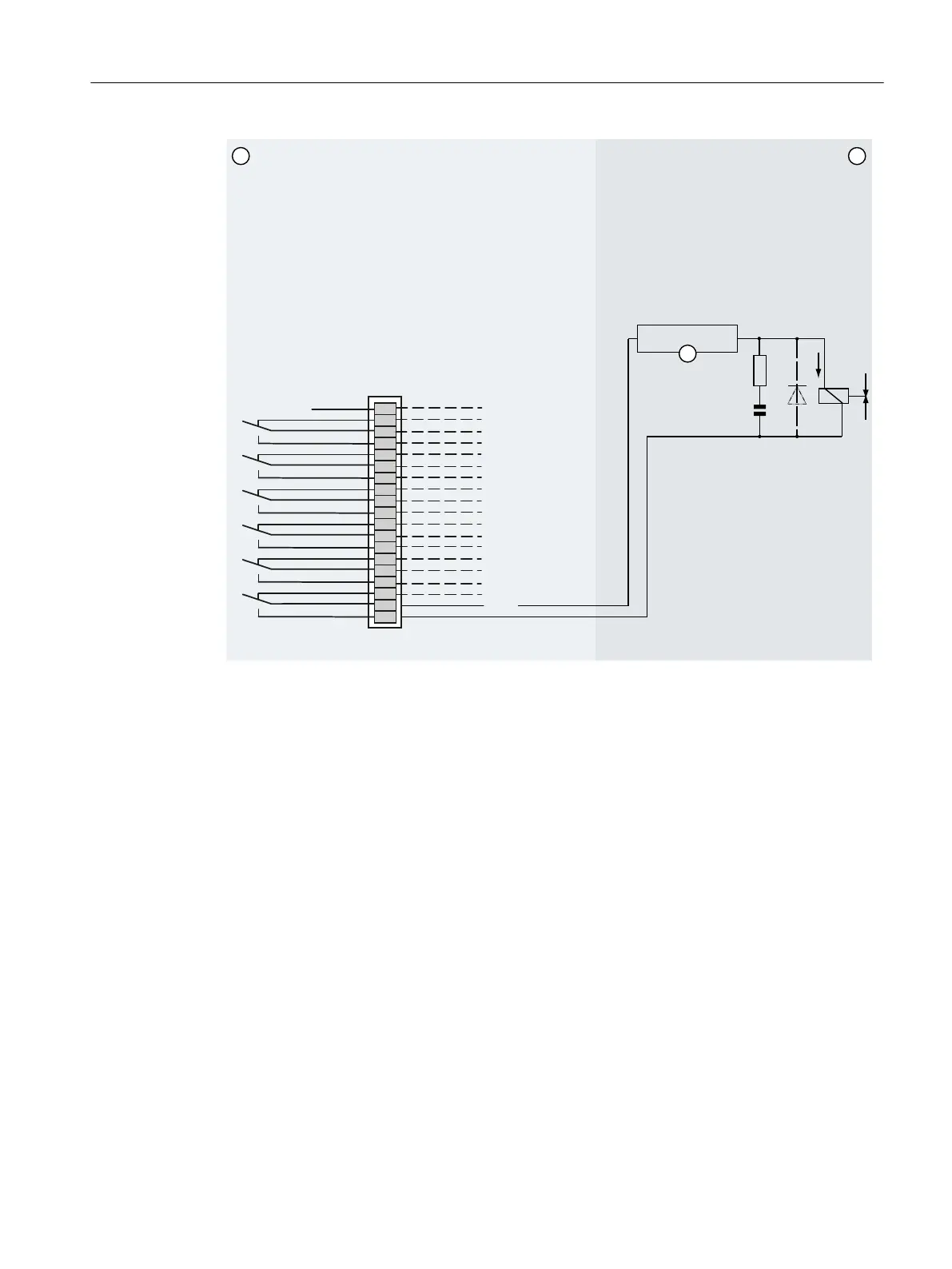
① Standard terminal block, terminal row A: Function in the analyzer
② Terminal end/spark suppression
③ Power supply unit
DO Digital outputs: Contact load max. 24 V/1.7 A, AC/DC. Shown relay contacts: relay coil has zero
current
Figure8-17 Wall-mounted device: Example of spark suppression on a relay contact
Observe the following information on spark suppression:
• To suppress sparks via relay contacts, you can use RC elements. In direct current operation,
you can also use a spark killer diode instead of the RC element.
• The RC element results in a drop-out delay for an inductive component, for example, a
solenoid valve. To rate the RC element accordingly, use the following rule of thumb:
– R[Ω]≈0.2xR
L
[Ω]
– C[μF]≈I
L
[A]
• You must use a non-polarized capacitor "C".
• When connecting the RC element, refer to the previous gure/gures.
Connecting the device
8.2Electrical connections
Wall-mounted device
Operating Instructions, 07/2023, A5E31930403-AB 119

 Loading...


