CAN bus cable
NOTICE
Confusing the connectors when connecting the modules
When connecting the modules to the CAN bus, confusing the connectors can lead to error
messages to the device.
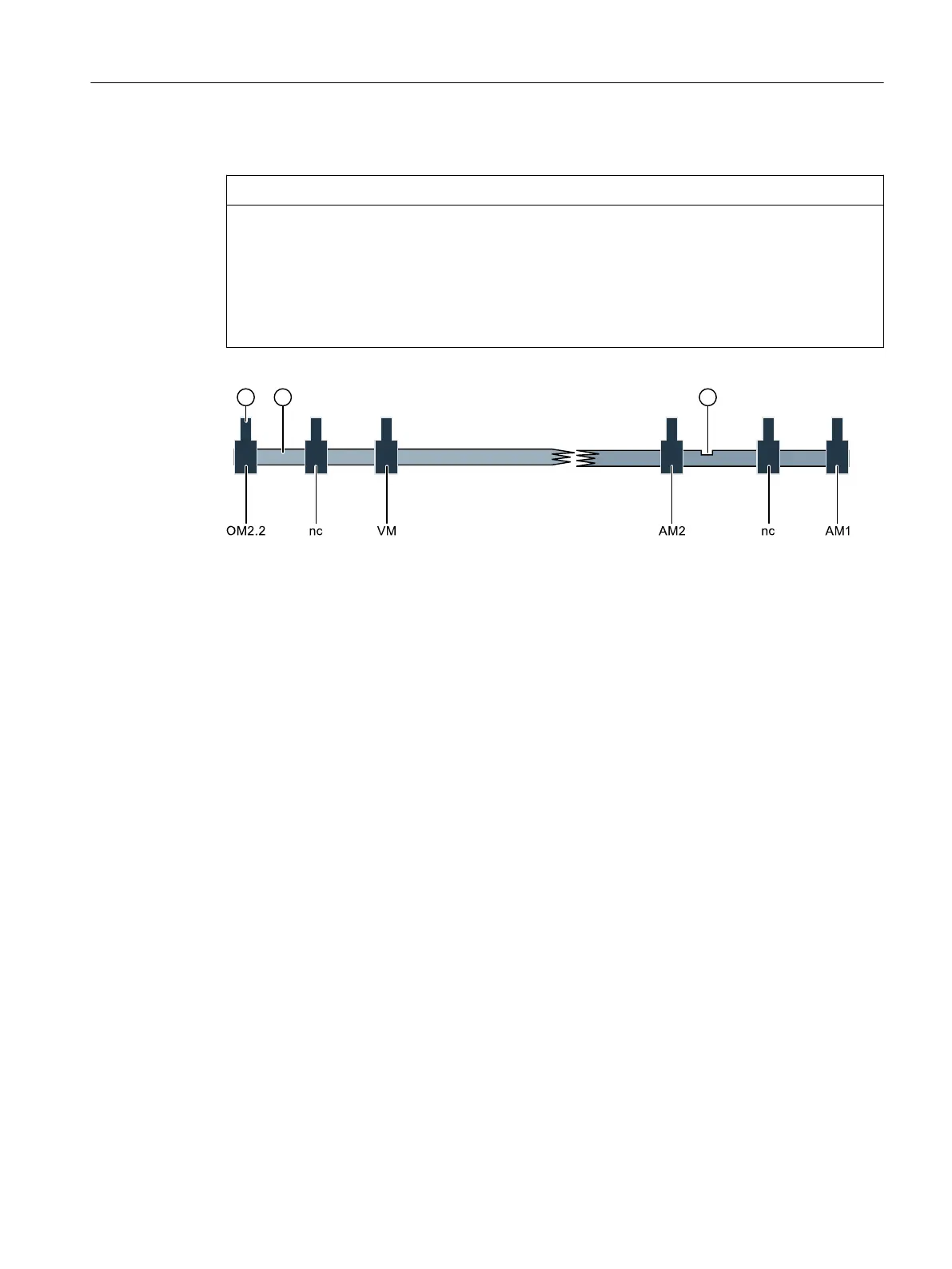
• For this reason, note the assignment shown in the following gure.
• Orient yourself in particular on the alignment of the CAN bus coding mark as of which the
connectors are coded dierently.
① CAN bus connectors
② CAN bus cable
③ Coding mark
OM2.2 Connectors of option module 2.2
PU Connectors of the processing unit
AM1/AM2 Connectors for the analyzer modules 1 and 2
nc Not assigned, without function
Figure7-1 Schematic representation of the CAN bus cable
Installing / removing and connecting analyzer and option modules
7.3Cables
Wall-mounted device
Operating Instructions, 07/2023, A5E31930403-AB 67

 Loading...


