3. Remove the equipotential bonding cable ④ from the blank plate of the respective slot.
Note: The cable for equipotential bonding ④ is no longer required after the analyzer
module ⑥ is installed.
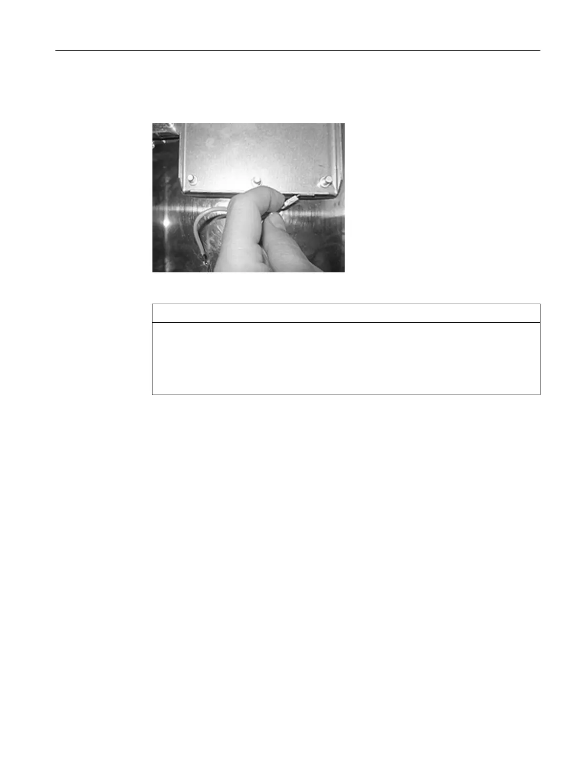
Figure7-3 Unlatching plug-in connectors at the cable equipotential bonding
NOTICE
Damage to the device through pulling the latched cable
Cables for equipotential bonding are equipped at their two ends with latching plug-in
connectors. Pulling on a latched cable can cause the plug-in connector to be torn o or its
contacts to be damaged.
• Before pulling out the plug connector, loosen the latch by pressing with your index nger.
4. Loosen the eight Torx screws ⑤ and remove the blank plate at the corresponding slot.
5. Check the at seal ③ for damage.
Replace the at seal ③ if it is damaged or porous.
6. Swivel the analyzer module ⑥ forward and insert it into the wall housing ①.
7. Secure the analyzer module ⑥ in the slot as follows:
– Use eight Torx screws on the base of the housing ⑤ with a torque of 0.8Nm.
– Use two Torx screws on the rear panel with a torque of 2.5Nm.
Installing / removing and connecting analyzer and option modules
7.4Installing analyzer modules, standard version
Wall-mounted device
Operating Instructions, 07/2023, A5E31930403-AB 69

 Loading...


