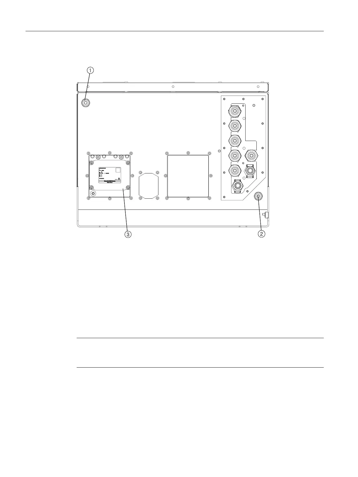
ULTRAMAT 7 high-temperature: Arrangement of the gas connections in the wall-mounted device
① Purging gas inlet
② Purging gas outlet
③ Slot of analyzer module 1: ULTRAMAT 7 high-temperature
1 Sample gas inlet
2 Sample gas outlet
3 Reference gas outlet
4 Reference gas inlet
Figure8-4 ULTRAMAT 7 gas connections high-temperature in the wall mounted device, bottom
Requirement on heated sample gas and reference gas lines
Note
Heated sample gas lines for analyzer modules, high-temperature version
The sample and reference gas must be fed to the analyzer module via heated external lines.
The gure below shows the dimensions of the heated gas line. The dimensions are specied
in millimeters.
Connecting the device
8.1Gas connections
Wall-mounted device
98 Operating Instructions, 07/2023, A5E31930403-AB

 Loading...


