2.7 Earth fault overcurrent protection in earthed systems (optional)
153
7SA522 Manual
C53000-G1176-C155-3
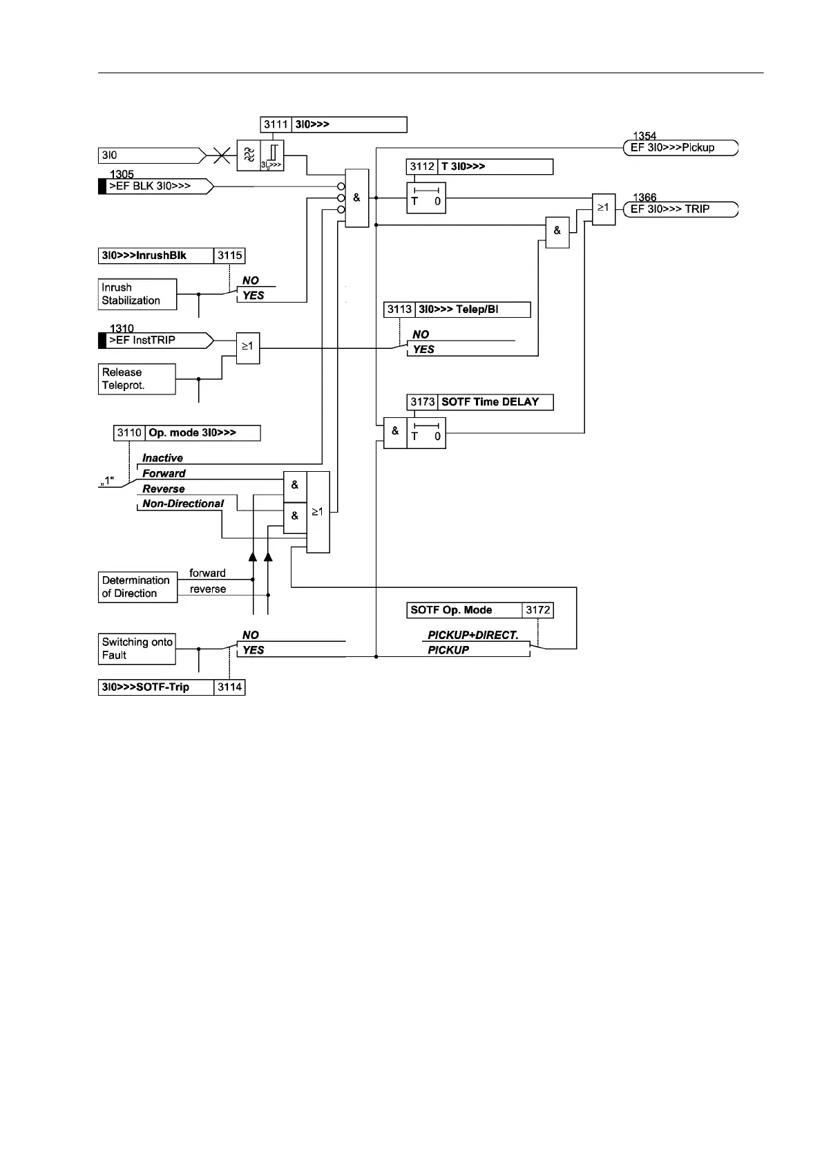
Figure 2-63 Logic diagram of the 3I
0
>>>–stage
Definite Time Very
High Set Current
Stage 3I
0
>>
The logic of the high set current stage 3I
0
>> is the same as that of the 3l
0
>>> stage.
In all references ,!!! must merely be replaced with ,!!. In all other respects
Figure 2-63 applies.
Definite Time Over-
current Stage 3I
0
>
The logic of the overcurrent current stage 3I
0
> is the same as that of the 3I
0
>>> stage.
In all references ,!!! must merely be replaced with ,!. In all other respects
Figure 2-63 applies. This stage operates with a specially optimized digital filter that
completely suppresses all harmonic components beginning with the 2nd harmonic.
Therefore it is particularly suited for a highly-sensitive earth fault detection.
A fourth, definite time stage can be implemented by setting the “inverse-time” stage
(refer to the next paragraph) to a definite-time stage.
Inverse Time
Overcurrent
Stage 3I
0P
The logic of the stages with inverse time delay functions operate the same as the re-
maining stages. This stage operates with a specially optimized digital filter that com-
pletely suppresses all harmonic components beginning with the 2nd harmonic. There-
fore it is particularly suited for a highly-sensitive earth fault detection. However, the

 Loading...


