2.8 Teleprotection for earth fault overcurrent protection (optional)
191
7SA522 Manual
C53000-G1176-C155-3
Digital Transmis-
sion
The following mode is possible with digital transmission using the protection data in-
terface:
6,*1$/Y3URW,QW = Directional Comparison Pickup.
At address )&77HOHS() the use of a teleprotection scheme can be
switched 21 or 2)). Address 180%(52)5(/$< indicates the number of ends
and must be set identically in all devices. The earth fault directional comparison pickup
scheme via the protection interface is only active if parameter 7HOHSURW()
was set to 6,*1$/Y3URW,QW for all
devices in a constellation.
Earth Fault Protec-
tion Prerequisites
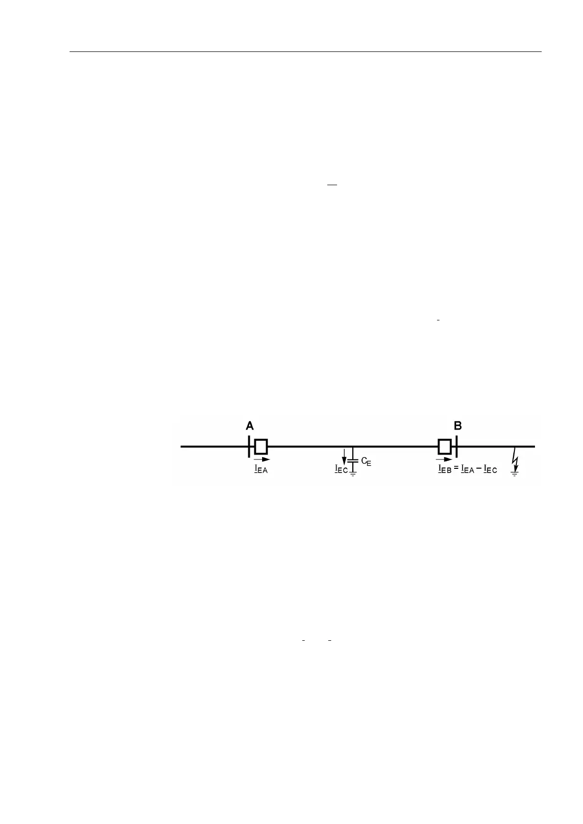
In the application of the comparison schemes, absolute care must be taken that both
line ends recognize an external earth fault (earth fault current flowing through) in order
to avoid a faulty echo signal in the case of the permissive schemes, or in order to
ensure the blocking signal in the case of the blocking scheme. If, during an earth fault
according to Figure 2-86, the protection at B does not recognize the fault, this would
be interpreted as a fault with single sided infeed from A (echo from B or no blocking
signal from B), which would lead to unwanted tripping by the protection at A. There-
fore, the earth fault protection features an earth fault stage ,R0LQ7HOHSURW (ad-
dress ). This stage must be set more sensitive than the earth current stage used
for the teleprotection. The larger the capacitive earth current (I
EC
in Figure 2-86) is the
smaller this stage must be set. On overhead lines a setting equal to 70% to 80% of the
earth current stage is usually adequate. On cables or very long lines where the capac-
itive currents in the event of an earth fault are of the same order of magnitude as the
earth fault currents the echo function should not be used or restricted to the case
where the circuit breaker is open; the blocking scheme should not be used under these
conditions at all.
Figure 2-86 Possible current distribution during external earth fault
On three terminal lines (teed feeders) it should further be noted that the earth fault
current is not equally distributed on the line ends during an external fault. The most
unfavourable case is shown in Figure 2-87. In this case, the earth current flowing in
from A is distributed equally on the line ends B and C. The setting value ,R0LQ
7HOHSURW (address ), which is decisive for the echo or the blocking signal, must
therefore be set smaller than one half of the setting value for the earth current stage
used for teleprotection. In addition, the above comments regarding the capacitive
earth current which is left out in Figure 2-87 apply. If the earth current distribution is
different from the distribution assumed here, the conditions are more favourable as
one of the two earth currents I
EB
or I
EC
must then be larger than in the situation de-
scribed previously.

 Loading...


