2.19 Monitoring function
317
7SA522 Manual
C53000-G1176-C155-3
Figure 2-139 Current symmetry monitoring
Broken Conductor A broken conductor of the protected line or in the current transformer secondary circuit
can be detected, if the minimum current 3ROH2SHQ&XUUHQW flows via the feeder. If
the smallest phase currents is below this threshold while the other phase currents are
above it, an interruption of a conductor may be assumed. If asymmetric current con-
ditions are also present (see margin heading “Current Symmetry”), the device issues
the indication ´)DLO&RQGXFWRUµ (FNo. 195).
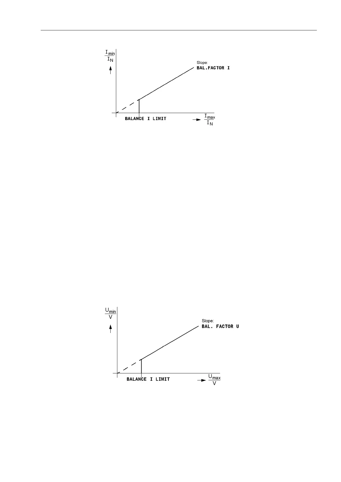
Voltage Symmetry During normal system operation (i.e. the absence of a short-circuit fault), symmetry
among the input voltages is expected. The symmetry is monitored in the device with
a magnitude comparison. The smallest phase-to-phase voltage is compared to the
largest. Asymmetry is recognized if:
| U
min
| / | U
max
| < %$/)$&7258 as long as | U
max
| > %$/$1&(8/,0,7
U
max
is the highest, U
min
the lowest of the three phase-to-phase voltages. The symme-
try factor %$/)$&7258 is the measure for the asymmetry of the conductor voltag-
es; the limit value %$/$1&(8/,0,7 is the lower limit of the operating range of this
monitoring (see Figure 2-140). Both settings are adjustable. The dropout ratio is about
97%.
After a settable time, this malfunction is signaled as ´)DLO8EDODQFHµ (FNo. 167).
Figure 2-140 Voltage symmetry monitoring
Voltage Phase
Sequence
The verification of the faulted phases and the phase preference, direction measure-
ment and polarization with quadrature voltages usually demand clockwise rotation of

 Loading...


