2 Functions
320
7SA522 Manual
C53000-G1176-C155-3
If such a voltage failure is recognized, the distance protection and all other functions
that operate on the basis of undervoltage (e.g. also weak infeed tripping) are blocked
until the voltage failure is removed; thereafter the blocking is automatically removed.
Definite time overcurrent emergency operation is possible during the voltage failure if
the overcurrent protection was configured accordingly (refer to Section 2.11).
Additional Mea-
sured Voltage
Failure Monitoring
If no measuring voltage is available after power-on of the device (e.g. because the
voltage transformers are not connected), the absence of the voltage can be detected
and reported by an additional monitoring function. Where circuit breaker auxiliary con-
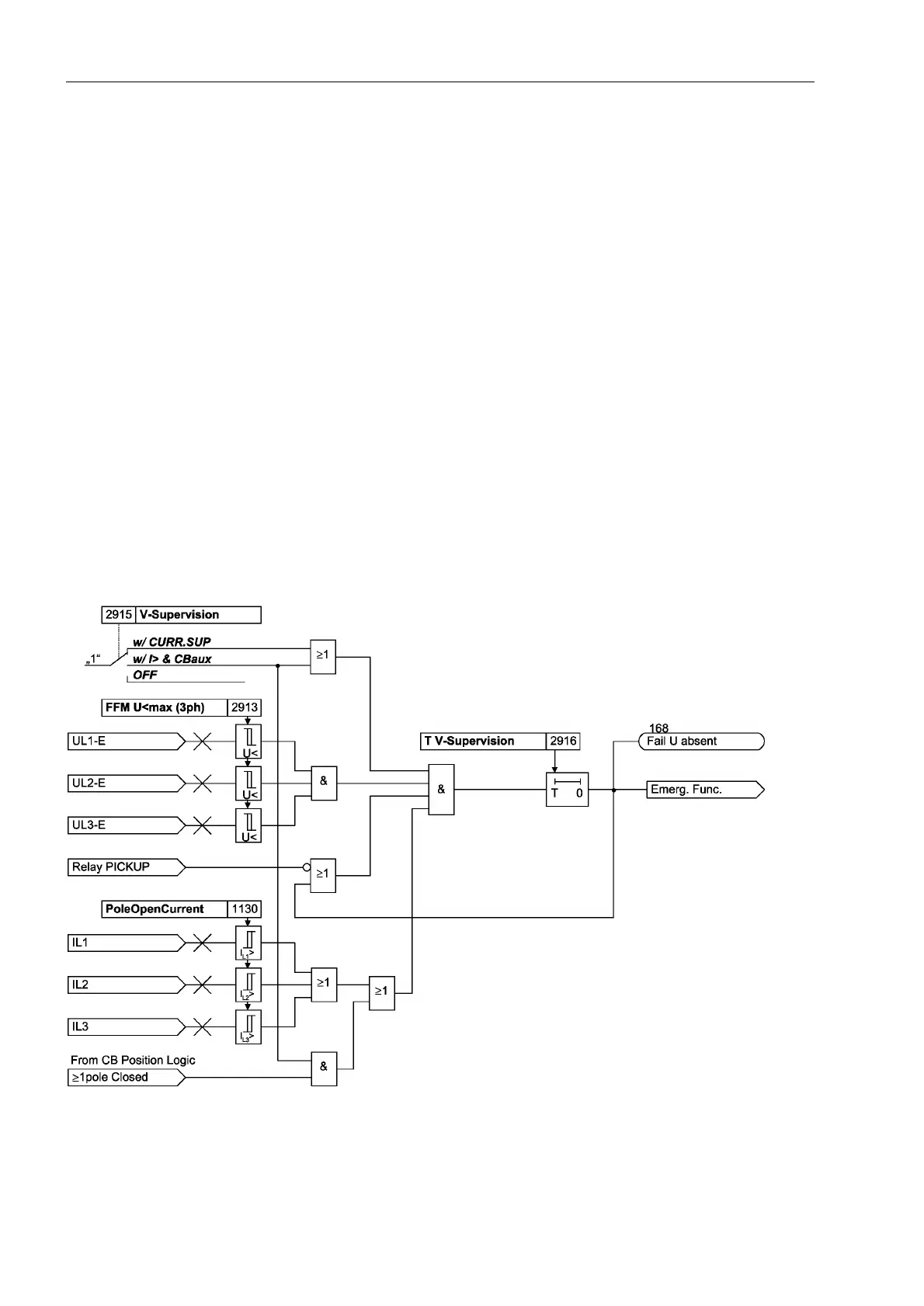
tacts are used, they should be used for monitoring as well. Figure 2-142 shows the
logic diagram of the measured voltage failure monitoring. A failure of the measured
voltage is detected if the following conditions are met at the same time:
• all three phase-to-earth voltages are smaller than ))08PD[SK,
• at least one phase current is larger than 3ROH2SHQ&XUUHQW or at least one
breaker pole is closed (can be set),
• no protection function has picked up,
• this condition persists for a settable time 796XSHUYLVLRQ (default setting: 3 s).
This time 796XSHUYLVLRQ is required to prevent that a voltage failure is detected
before the protection picks up.
If a failure is detected by these criteria, the annunciation 168 ´)DLO8DEVHQWµ is
output, and the device switches to emergency operation (see Section 2.11).
Figure 2-142 Logic diagram of the additional measured voltage failure monitoring

 Loading...


