2.19 Monitoring function
327
7SA522 Manual
C53000-G1176-C155-3
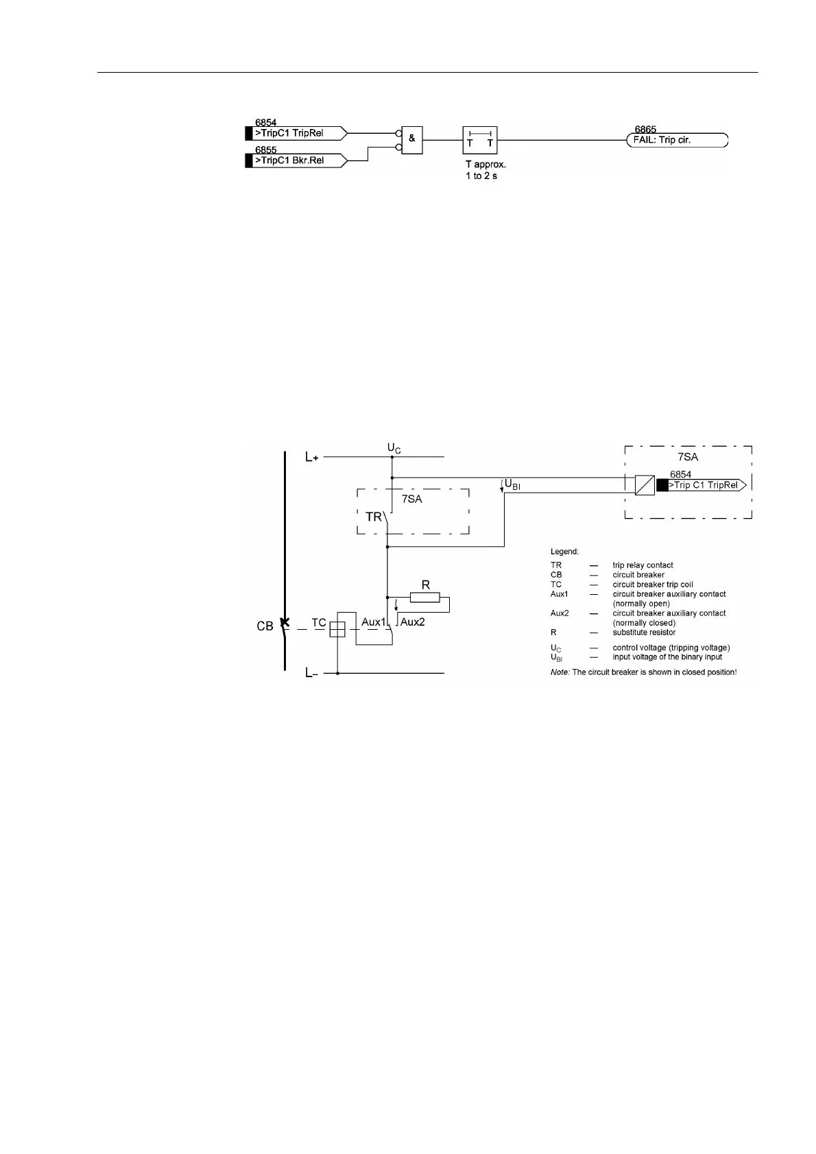
Figure 2-144 Logic diagram of the trip circuit monitoring with two binary inputs
Monitoring with
One Binary Input
The binary input is connected in parallel to the respective command relay contact of
the protection device according to Figure 2-145. The circuit breaker auxiliary contact
is bridged with a high-ohm substitute resistor R.
The control voltage for the circuit breaker should be at least twice as high as the
minimum voltage drop at the binary input (U
Ctrl
> 2 · U
BImin
). Since at least 19 V are
needed for the binary input, the monitor can be used with a system control voltage of
over 38 V.
A calculation example for the resistance shunt R is shown in the configuration notes
in Section “Mounting and Connections”, margin “Trip Circuit Supervision”.
Figure 2-145 Principle of the trip circuit monitoring with one binary input
During normal operation, the binary input is activated (logical condition “H”) when the
trip contact is open and the trip circuit is intact, because the monitoring circuit is closed
by either the circuit breaker auxiliary contact (if the circuit breaker is closed) or through
the bypass resistor R. Only as long as the trip contact is closed, the binary input is
short circuited and thereby deactivated (logical condition “L”).
If the binary input is permanently deactivated during operation, an interruption in the
trip circuit or a failure of the (trip) control voltage can be assumed.
The trip circuit monitor does not operate during system faults. A momentary closed
tripping contact does not lead to a failure message. If however other trip relay contacts
from different devices are connected in parallel in the trip circuit, the failure alarm must
be delayed by $ODUP'HOD\ (refer also to Figure 2-146). After the fault in the trip
circuit is removed, the alarm is reset automatically after the same time.

 Loading...


