2 Functions
352
7SA522 Manual
C53000-G1176-C155-3
er) positively. Using parameter address 34VLJQ the signs for these compo-
nents can be inverted.
The computation of the operational measured values is also executed during an exis-
tent system fault in intervals of approx. 0.5s.
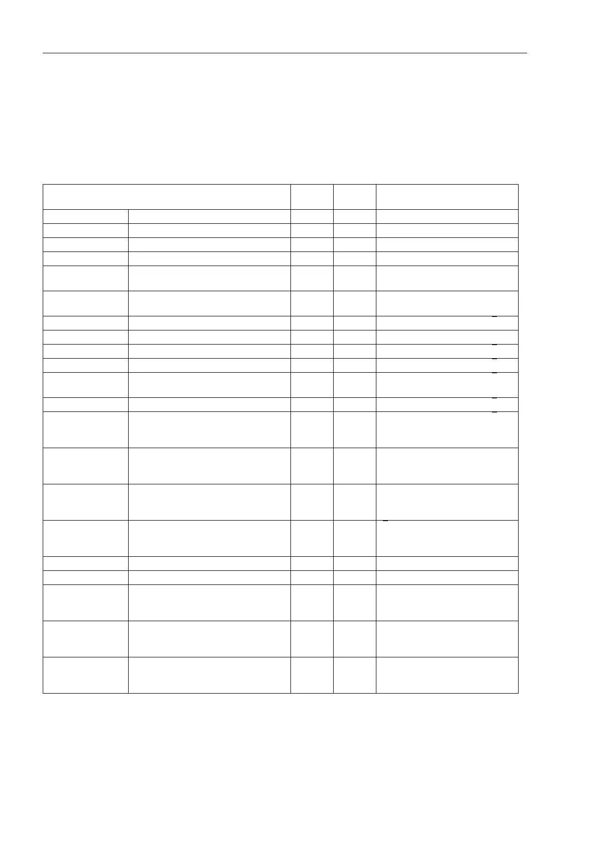
Table 2-14 Operational measured values of the local device
1)
according to address 1104
2)
according to address 1103
3)
considering factor 221 I4/Iph CT
Measured Values primary second-
ary
% referred to
I
L1
, I
L2
, I
L3
Phase currents S S Rated operational current
1)
I
EE
Sensitive earth current S mA Rated operational current
3)1)
3I
0
— calculated Earth current S S Rated operational current
1)
3I
0
— measured Earth current A A Rated operational current
3)1)
I
1
, I
2
Positive and negative sequence compo-
nent of currents
S S Rated operational current
1)
I
Y
, I
P
Transformer Starpoint Current or Earth
Current of the Parallel Line
S S Rated operational current
3)1)
U
L1-E
, U
L2-E
, U
L3-E
Phase-to-earth voltages kV V Operational rated voltage / √3
2)
U
L1-L2
, U
L2-L3
, U
L3-L1
Phase-to-phase voltages kV V Operational rated voltage
2)
3U
0
Displacement Voltage kV V Operational rated voltage / √3
2)
U
0
Zero-sequence voltage kV V Operational rated voltage / √3
2)
U
1
, U
2
Positive and negative sequence compo-
nent of voltages
kV V Operational rated voltage / √3
2)
U
X
Voltage at measuring input U
4
kV V Operational rated voltage / √3
2)
U
1compounded
Positive sequence component of voltag-
es at the remote end (if compounding is
active in voltage protection)
kV kV Operational rated voltage / √3
2)
R
L1-E
, R
L2-E
,
R
L3-E
, R
L1-L2
,
R
L1-L2
, R
L3-L1
Operational resistance of all loops Ω Ω —
X
L1-E
, X
L2-E
,
X
L3-E
,X
L1-L2
,
X
L2-L3
, X
L3-L1
Operational reactance of all loops Ω Ω —
S, P, Q Apparent, active and reactive power MVA,
MW,
MVAR
— √3
·U
N
· I
N
operational rated quanti-
ties
1)2)
f Frequency Hz Hz Rated system frequency
cos ϕ Power factor (abs) (abs) —
U
line
, U
bus
, U
diff
Line voltage, busbar voltage and
voltage difference (for synchronism
check)
kV — —
f
line
, f
bus
, f
diff
Line voltage, busbar frequency and
voltage difference (for synchronism
check)
Hz — —
ϕ
diff
Amount of phase angle difference
between line and busbar (for synchro-
nism check)
°
——

 Loading...


