3 Mounting and Commissioning
374
7SA522 Manual
C53000-G1176-C155-3
Where:
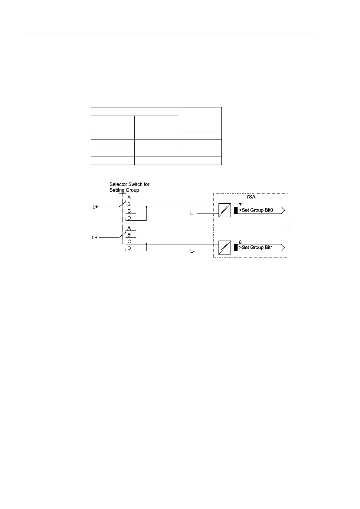
No = not energized
Yes = energized
Table 3-1 Changing Setting Groups with Binary Inputs
Figure 3-1 Connection diagram (example) for setting group switching with binary inputs
Trip Circuit Super-
vision
It must be noted that two binary inputs or one binary input and one bypass resistor R
must be connected in series. The pick-up threshold of the binary inputs must therefore
be substantially below half
the rated control DC voltage.
If two binary inputs are used for the trip circuit supervision, these binary inputs must
be isolated, i.o.w. not be communed with each other or with another binary input.
If one binary input is used, a bypass resistor R must be used (refer to Figure 3-2). This
resistor R is connected in series with the second circuit breaker auxiliary contact
(Aux2), to also allow the detection of a trip circuit failure when the circuit breaker aux-
iliary contact 1 (Aux1) is open, and the command relay contact has reset. The value
of this resistor must be such that in the circuit breaker open condition (therefore Aux1
is open and Aux2 is closed) the circuit breaker trip coil (TC) is no longer picked up and
binary input (BI1) is still picked up if the command relay contact is open.
Binary Input Active Group
>Set Group Bit
0
>Set Group Bit
1
No No Group A
Yes No Group B
No Yes Group C
Yes Yes Group D

 Loading...


