3.1 Mounting and Connections
385
7SA522 Manual
C53000-G1176-C155-3
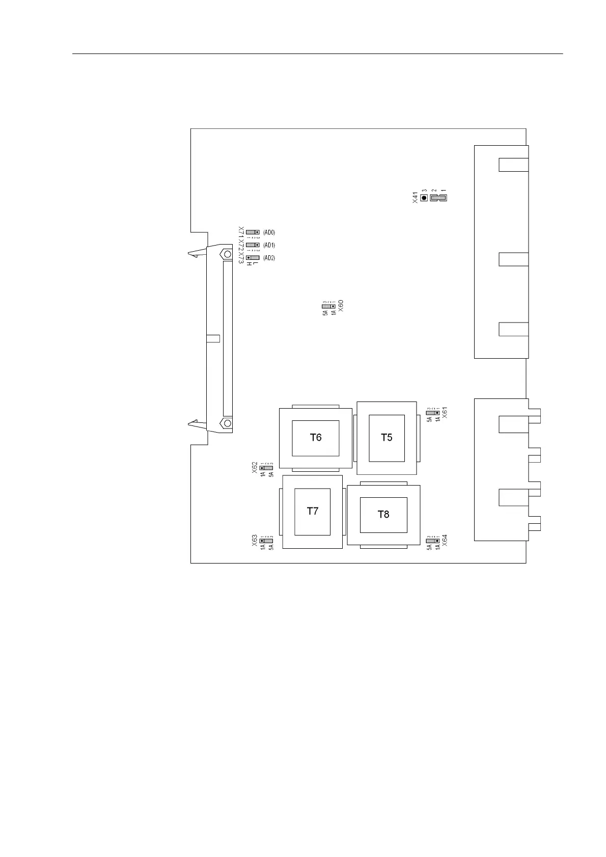
Board C-I/O-2 The layout of the PCB for the C-I/O-2 board is shown in Figure 3-7.
Figure 3-7 Input/output board C–I/O-2 with representation of jumper settings required for
checking configuration settings
The contact type of binary output BO13 can be changed from normally open to nor-
mally closed (see also overview diagrams in section A.2 of the Appendix).
with housing size
1
/
2
: No. 3 in Figure 3-3, slot 33
with housing size
1
/
1
: No. 3 in Figure 3-4, slot 33 right.

 Loading...


