3 Mounting and Commissioning
388
7SA522 Manual
C53000-G1176-C155-3
Table 3-10 Exchange Interface Modules
The order numbers of the exchange modules can be found in the Appendix in Section
A.1, Accessories.
RS232 Interface Interface RS232 can be modified to interface RS485 and vice versa (see Figures 3-9
and 3-10).
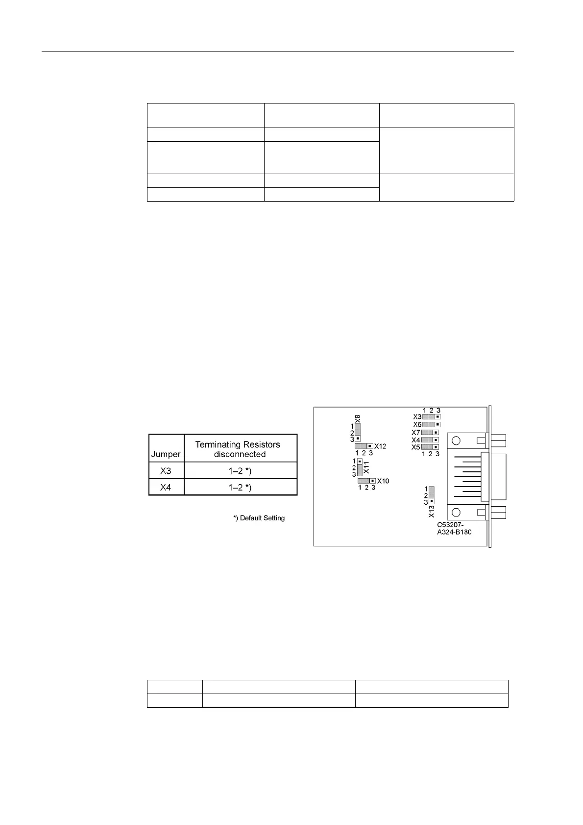
Figure 3-8 shows the C-CPU-1 PCB with the layout of the modules.
The following figure shows the location of the jumpers of interface RS232 on the inter-
face module.
Devices in surface mounting housing with fibre optics connection have their fibre
optics module housed in the console housing. The fibre optics module is controlled via
a RS232 interface module at the associated CPU interface slot. For this application
type the jumpers X12 and X13 on the RS232 module are plugged in position 2-3.
Figure 3-9 Location of the jumpers for configuration of RS232
Terminating resistors are not required for RS232. They are disconnected.
With jumper X11, CTS (Clear-to-Send) is activated which is necessary for modem
communication is enabled.
Table 3-11 Jumper setting for CTS (Clear To Send, flow control) on the interface module
1)
Default Setting
Interface Mounting location / inter-
face
Exchange module
System Interface B Only interface modules that can
be ordered in our facilities via the
order key (see also Appendix,
Section A.1).
Service Interface C
Protection Data Interface 1 D FO5 to FO8
Protection Data Interface 2 E
Jumper /CTS from Interface RS232 /CTS controlled by /RTS
X11 1-2 2-3
1)

 Loading...


