2.1 General
53
7SA522 Manual
C53000-G1176-C155-3
may a smaller setting be useful. A more detailed explanation of parallel line compen-
sation can be found in Section 2.2.1 under distance protection.
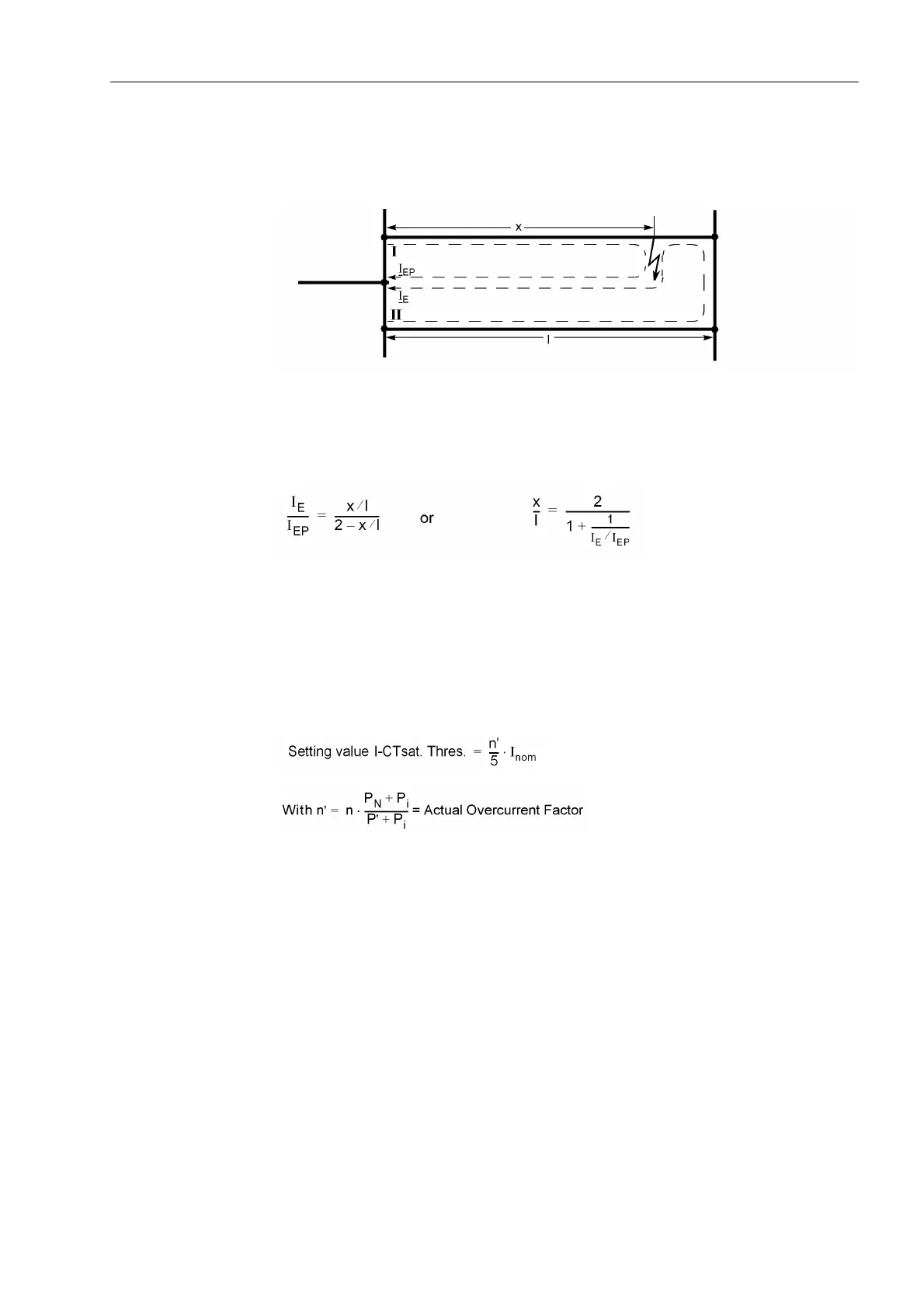
Figure 2-4 Reach with parallel line compensation at II
The current ratio may also be calculated from the desired reach of the parallel line
compensation and vice versa. The following applies (refer to Figure 2-4):
Current
Transformer
Saturation
The 7SA522 contains a saturation detector which largely eliminates the measuring
errors resulting from the saturation of the current transformers. The threshold above
which it picks up can be set in address ,&7VDW7KUHV. This is the current
level above which saturation may be present. The setting ∞ disables the saturation de-
tector. This setting is only possible via DIGSI
®
at Additional Settings. If current trans-
former saturation is expected, the following equation may be used as a thumb rule for
this setting:
P
N
= Rated CT burden [VA]
P
i
= Rated CT internal burden [VA]
P' = Actual connected burden (protection device + connection cable)
Circuit Breaker
Status
Information regarding the circuit breaker position is required by various protection and
supplementary functions to ensure their optimal functionality. The device has a circuit
breaker status recognition which processes the status of the circuit breaker auxiliary
contacts and contains also a detection based on the measured currents and voltages
for opening and closing (see also Section 2.20.1).
In address the residual current is set 3ROH2SHQ&XUUHQW, which will definitely
not be exceeded when the circuit breaker pole is open. If parasitic currents (e.g.
through induction) can be excluded when the circuit breaker is open, this setting may
be very sensitive. Otherwise this setting must be increased correspondingly. Usually

 Loading...


