2.2 Distance protection
93
7SA522 Manual
C53000-G1176-C155-3
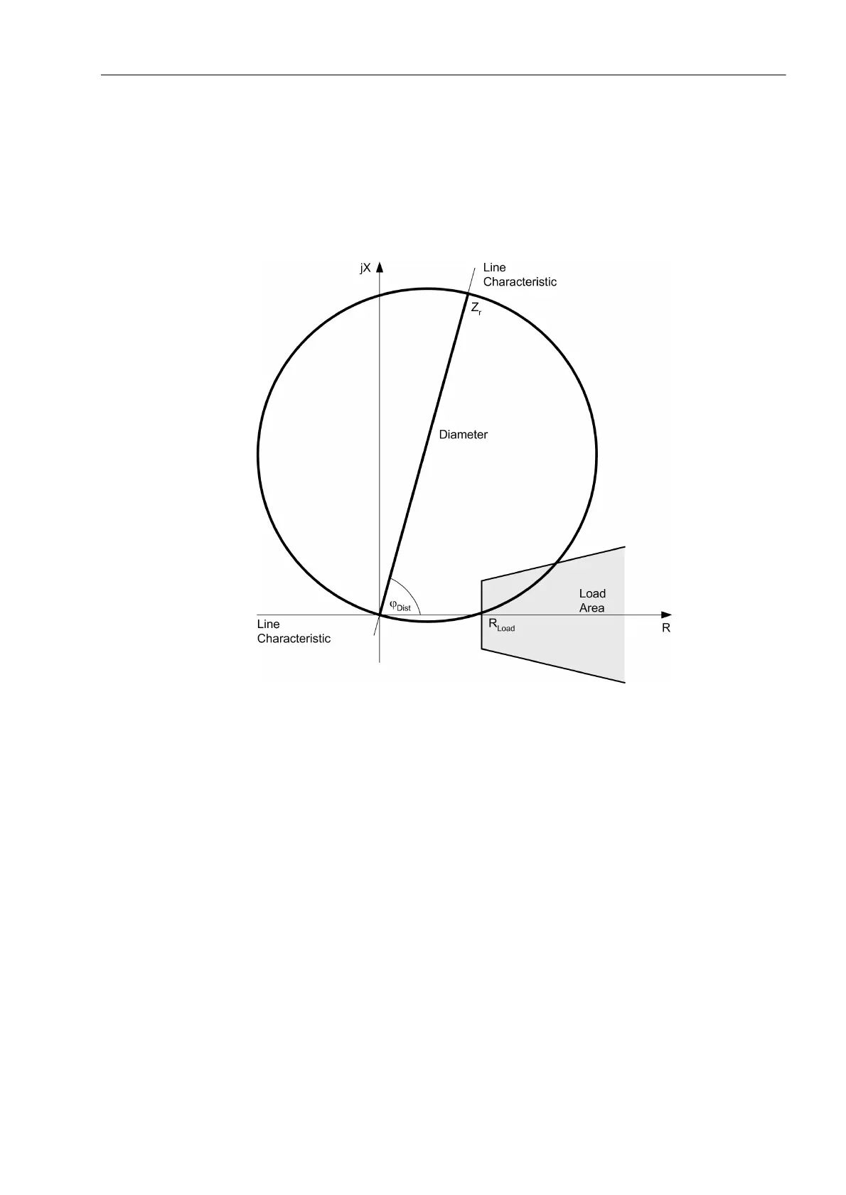
'LVWDQFH$QJOH which usually corresponds to the line angle ϕ
Line
. A load trap-
ezoid with the setting R
Load
and ϕ
Load
may be used to cut the area of the load imped-
ance out of the circle. The reach Z
r
may be separately set for each zone; the inclination
angle ϕ
Dist
as well as the load impedance parameters R
Load
, and ϕ
Load
are common to
all zones. As the circle intersects the origin of the coordinate system, a separate direc-
tional characteristic is not required.
Figure 2-25 Basic shape of a MHO-circle-characteristic
Polarized MHO
Circle
As is the case with all characteristics that pass through the origin of the coordinate
system, the MHO circle boundary close to the origin itself is also not defined as the
measured voltage is zero or too small to be evaluated in this case. For this reason, the
MHO circle is polarized. The polarization determines the lower zenith of the circle, i.e.
the lower intersection of the diameter line with the circle. The upper zenith which is de-
termined by the reach setting Z
r
remains unchanged. Immediately after fault inception,
the short-circuit voltage is disturbed by transients; the voltage memorized prior to fault
inception is therefore used for polarization. This causes a displacement of the lower
zenith by an impedance corresponding to the memorized voltage (refer to Figure 2-
26). When the memorized short-circuit voltage is too small, an unfaulted voltage is
used. In theory this voltage is perpendicular to the voltage of the faulted loop for both
phase-earth loops as well as phase-phase loops. This is taken into account by the cal-
culation by means of a 90° rotation. The unfaulted loop voltages also cause a displace-
ment of the lower zenith of the MHO circle.

 Loading...


