2 Functions
94
7SA522 Manual
C53000-G1176-C155-3
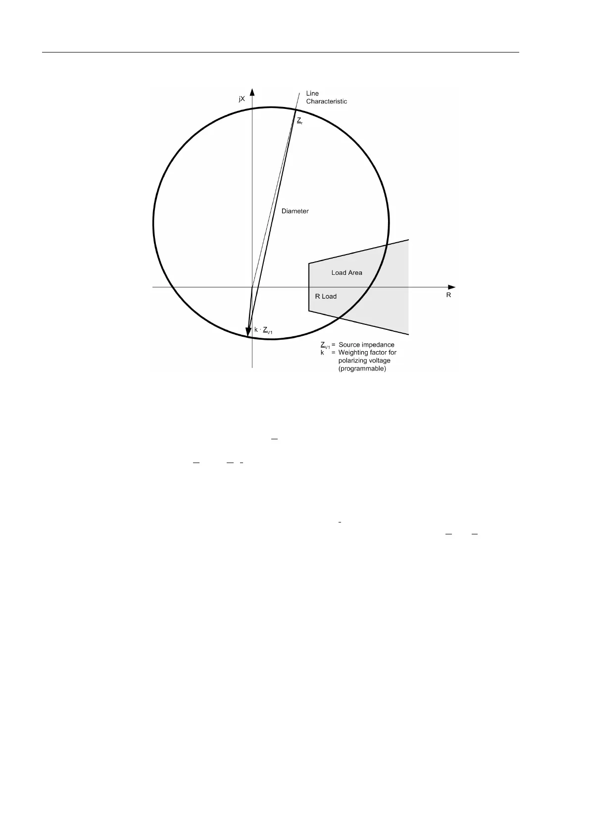
Figure 2-26 Basic MHO circle
Characteristics of
the MHO Circle
As the quadrature or memorized voltage (without load transfer) equals the corre-
sponding generator voltage E
and does not change after fault inception (refer also to
Figure 2-27), the lower zenith is shifted in the impedance diagram by the polarizing
quantity k·Z
V1
=k·E
1
/I
1
. The upper zenith is still defined by the setting value Z
r
. For the
fault location F
1
(Figure 2-27a) the short-circuit location is in the forward direction and
the source impedance is in the reverse direction. All fault locations, right up to the
device mounting location (current transformers) are clearly inside the MHO circle
(Figure 2-27b). If the current is reversed, the zenith of the circle diameter changes
abruptly (Figure 2-27c). A reversed current I
2
now flows via the measuring location
(current transformer) which is determined by the source impedance Z
S2
+ Z
L
. The
zenith Z
r
remains unchanged; it now is the lower boundary of the circle diameter. In
conjunction with load transport via the line, the zenith vector may additionally be
rotated by the load angle.

 Loading...


