Functions
2.11 Ground Fault Protection 64, 67N(s), 50N(s), 51N(s)
SIPROTEC, 7SK80, Manual
E50417-G1140-C344-A4, Release date 08.2010
189
2.11.3 Ground Fault Location
Application Example
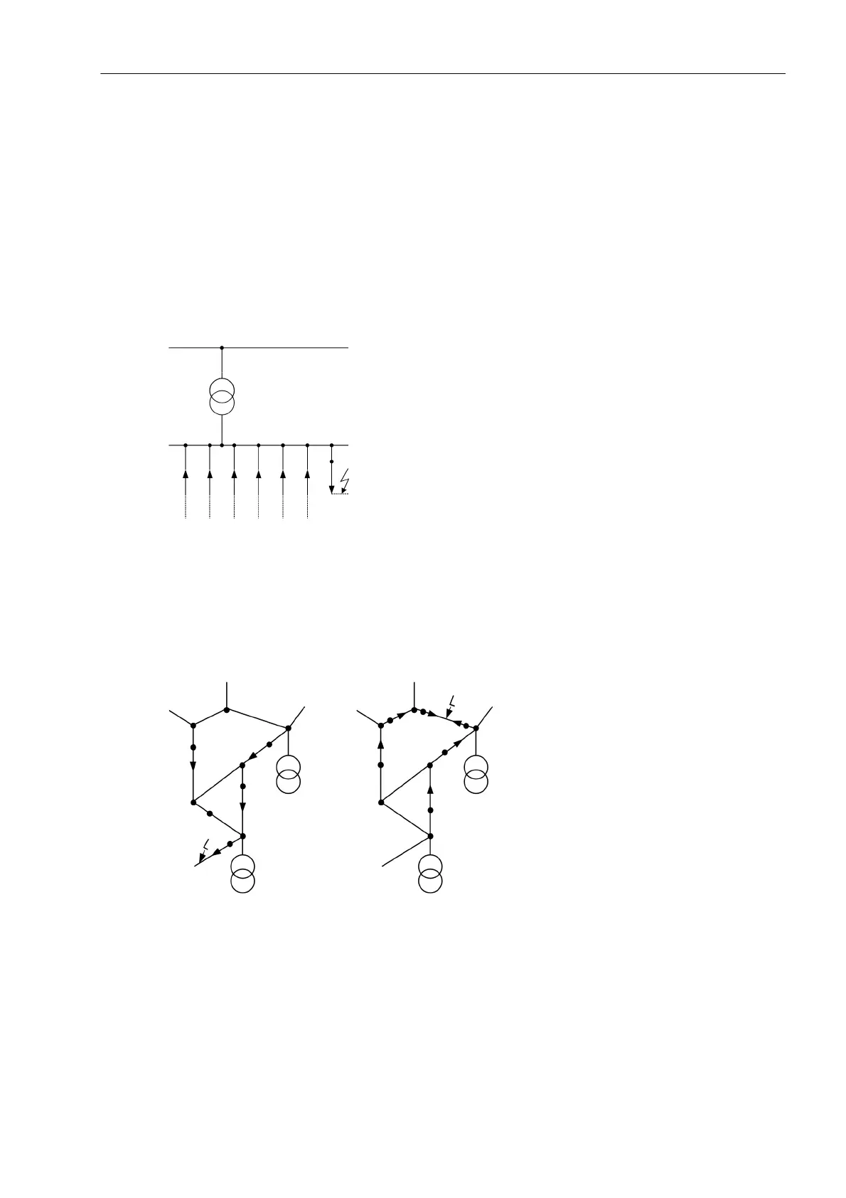
Directional determination may often be used to locate ground faults. In radial systems, locating the ground fault
is relatively simple. Since all feeders from a common bus (Figure 2-68) deliver a capacitive charging current,
nearly the total ground fault current of the system is available at the measuring point of the faulty line in the
ungrounded system. In the resonant grounded system it is the residual wattmetric current of the Petersen coil
that flows via the measuring point. Therefore, on the faulty cables a clear "forward" decision is made whereas
in other feeders either "reverse" direction is sent back or no measurement is carried out in case ground current
is too low. Definitely the faulty line can be determined clearly.
Figure 2-68 Location of ground faults in a radial network
In meshed or looped systems, the measuring points of the faulty line also receive the maximum ground fault
current (residual current). Only in this line, "forward" direction is signaled at both ends (Figure 2-69). The rest
of the direction indications in the system may also be useful for ground fault detection. However, some indica-
tions may not be given when the ground current is too low.
Figure 2-69 Determination of the ground fault location basing on directional indicators in the meshed
system

 Loading...


