Functions
2.2 Overcurrent Protection 50, 51, 50N, 51N
SIPROTEC, 7SK80, Manual
E50417-G1140-C344-A4, Release date 08.2010
74
Manual Close Mode (phases,Ground)
When a circuit breaker is closed onto a faulted line, a high-speed trip by the circuit breaker is usually desired.
For overcurrent or high-set Element the delay may be bypassed via a Manual Close pulse, thus resulting in
instantaneous tripping. This pulse is prolonged by at least 300 ms. To enable the device to react properly on
occurrence of a fault in the phase elements, address 1213 MANUAL CLOSE has to be set accordingly. Corre-
spondingly, address 1313 MANUAL CLOSE is considered for the ground path address. Thus, the user deter-
mines for both elements, the phase and the Ground element, what pickup value is active with what delay when
the circuit breaker is closed manually.
External Control Command
If the manual close signal is not sent from 7SK80 device, i.e. neither via the built-in operator interface nor via
a serial interface, but directly from a control acknowledgment switch, this signal must be passed to a 7SK80
binary input, and configured accordingly („>Manual Close“), so that the Element selected for MANUAL
CLOSE can become effective. The alternative Inactive means that all elements operate as per configuration
even with manual close and do not get special treatment.
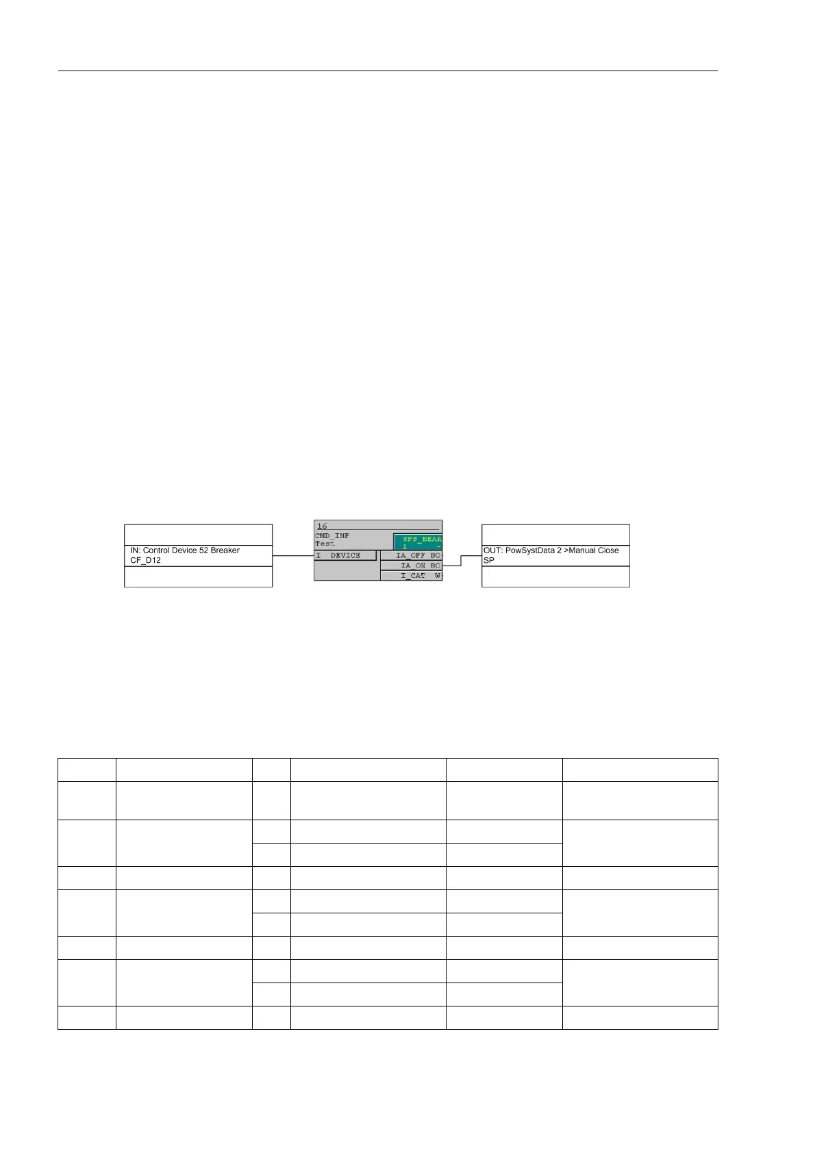
Internal Control Function
If the manual close signal is sent via the internal control function of the device, an internal connection of infor-
mation has to be established via CFC (interlocking task level) using the CMD_Information block (see Figure 2-
16).
Figure 2-16 Example for the generation of a manual close signal using the internal control function
2.2.11 Settings
Addresses which have an appended "A" can only be changed with DIGSI, under "Display Additional Settings".
The table indicates region-specific default settings. Column C (configuration) indicates the corresponding sec-
ondary nominal current of the current transformer.
Addr. Parameter C Setting Options Default Setting Comments
1201 FCT 50/51 ON
OFF
ON 50, 51 Phase Time Over-
current
1202 50-2 PICKUP 1A 0.10 .. 35.00 A; ∞ 4.00 A 50-2 Pickup
5A 0.50 .. 175.00 A; ∞ 20.00 A
1203 50-2 DELAY 0.00 .. 60.00 sec; ∞ 0.00 sec 50-2 Time Delay
1204 50-1 PICKUP 1A 0.10 .. 35.00 A; ∞ 1.00 A 50-1 Pickup
5A 0.50 .. 175.00 A; ∞ 5.00 A
1205 50-1 DELAY 0.00 .. 60.00 sec; ∞ 0.50 sec 50-1 Time Delay
1207 51 PICKUP 1A 0.10 .. 4.00 A 1.00 A 51 Pickup
5A 0.50 .. 20.00 A 5.00 A
1208 51 TIME DIAL 0.05 .. 3.20 sec; ∞ 0.50 sec 51 Time Dial

 Loading...


