Mounting and Commissioning
3.3 Commissioning
SIPROTEC, 7SK80, Manual
E50417-G1140-C344-A4, Release date 08.2010
317
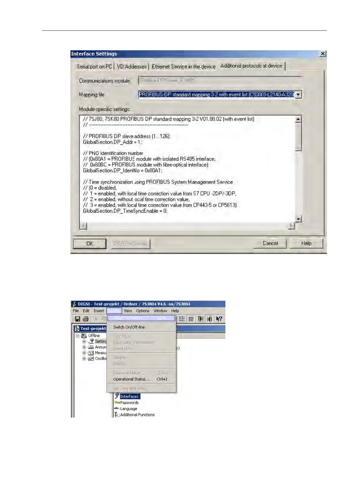
Figure 3-25 Module-specific settings
Then, transfer the data to the protection device (see the following figure).
Figure 3-26 Transmitting data

 Loading...


