Functions
2.1 General
SIPROTEC, 7SK80, Manual
E50417-G1140-C344-A4, Release date 08.2010
36
Current Connection (Power System Data)
Via parameter 251 CT Connect. a special connection of the current transformers can be determined.
The standard connection is A, B, C, (Gnd). It may only be changed if the device is set to measure one or
more ground currents via two current inputs. The standard connection has to be used in all other cases.
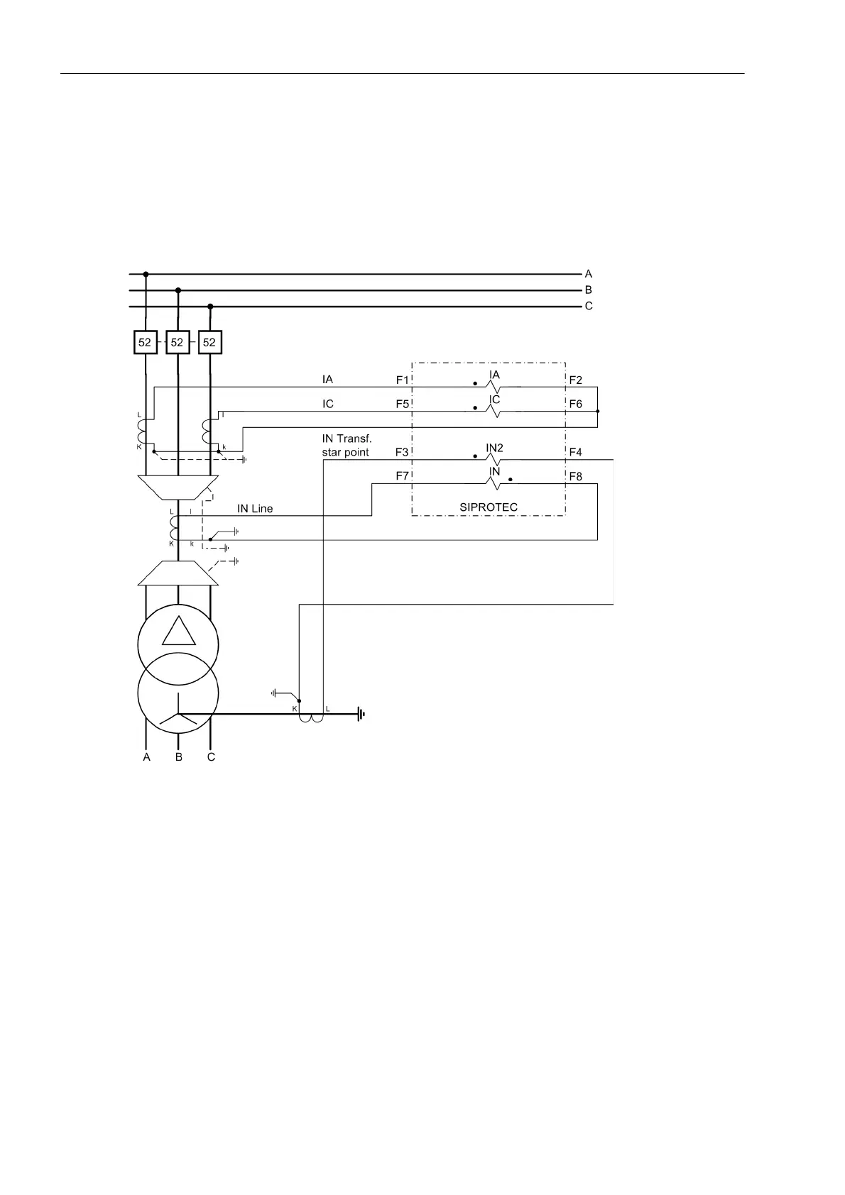
The following picture illustrates such a special connection.
Figure 2-3 Measurement of two ground currents, example
The phase currents I
A
and I
C
must be connected to the first current input (terminals F1, F2) and to the third
(terminals F5, F6) The ground current IN or INS is connected to the fourth input (terminals F7, F8) as usual, in
this case the ground current of the line. A second ground current, in this case the transformer starpoint current,
is connected to the second current input IN2 (terminals F3, F4).
The settings A,G2,C,G; G->B or A,G2,C,G; G2->B are used here. They both define the connection of a
ground current IN2 to the second current input (terminals F3, F4). The settings only differ in the calculation of
I
B
. In the case of A,G2,C,G; G->B, the phase current I
B
is determined from the phase currents I
A
and I
C
and
from the measured ground current IN or INS at the fourth current input. In the case of A,G2,C,G; G2->B, the
phase current I
B
is determined from the phase currents I
A
and I
C
and from the measured ground current IN2
at the second current input. This setting is only possible for devices with sensitive ground current transformer.
Therefore, the current IN2 at the second current input is referred to IN in the flexible protection functions and
in the operational measured values. The sensitive ground current at the fourth current input is referred to INS.
The setting must be selected according to the system requirements.

 Loading...


