Technical Data
4.15 Ground Fault Protection 64, 67N(s), 50N(s), 51N(s)
SIPROTEC, 7SK80, Manual
E50417-G1140-C344-A4, Release date 08.2010
378
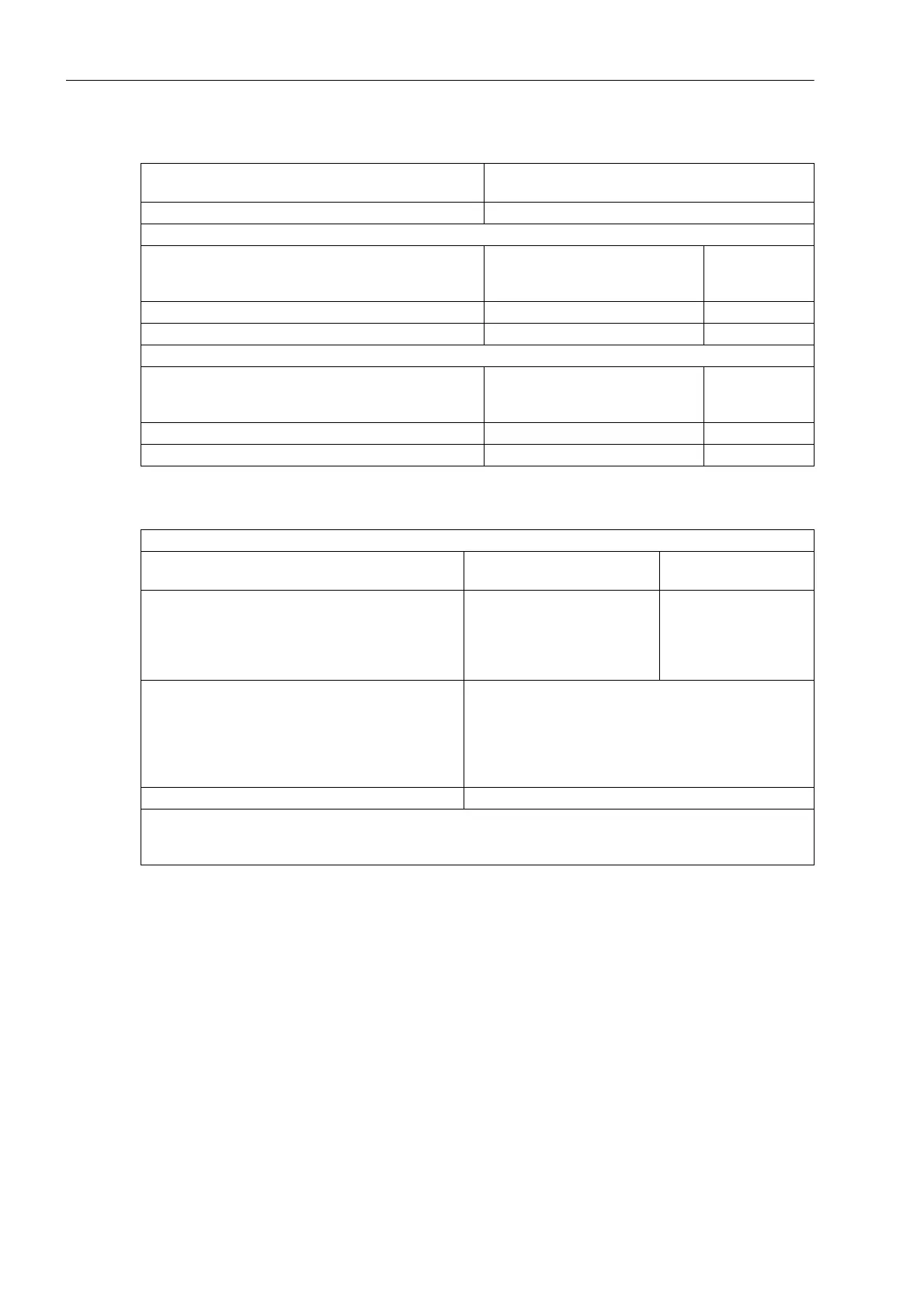
Direction Determination for all Types of Ground Fault with V0 ϕ / I0 ϕ Measurement
Angle Correction
Direction measurement - I
N
and V
N
measured
- 3I
0
and 3V
0
calculated
Measuring principle U0 / I0 phase angle measurement
50Ns-1 element
Minimum voltage 50Ns-1 Vmin
V0 measured
3V0 calculated
0.4 V to 50 V
10 V to 90 V
Increments 0.1 V
Increments 1 V
Phase angle 50Ns-1 Phi - 180° to 180° Increments 1°
Delta phase angle 50Ns-1 DeltaPhi 0° to 180° Increments 1°
50Ns-2 element
Minimum voltage 50Ns-2 Vmin
V0 measured
3V0 calculated
0.4 V to 50 V
10 V to 90 V
Increments 0.1 V
Increments 1 V
Phase angle 50Ns-2 Phi - 180° to 180° Increments 1°
Delta phase angle 50Ns-2 DeltaPhi 0° to 180° Increments 1°
Angle correction for cable converter in two operating points F1/I1 and F2/I2:
Angle correction F1, F2
(for resonant-grounded system)
0.0° to 5.0° Increments 0.1°
Current values I1, I2 for angle correction
for sensitive 1 A transformer
for sensitive 5 A transformer
for normal 1 A transformer
for normal 5 A transformer
0.001 A to 1.600 A
0.005 A to 8.000 A
0.05 A to 35.00 A
0.25 A to 175.00 A
Increments 0.001 A
Increments 0.005 A
Increments 0.01 A
Increments 0.05 A
Measurement tolerance
sensitive
non-sensitive
3 % of setting value or 1 mA for I
Nom
= 1A, or 5mA for
I
Nom
= 5 A
for setting values < 10 mA approx. 20 %
3 % of setting value or 15 mA for I
Nom
= 1 A, or 75 mA for
I
Nom
= 5 A
Angle tolerance 3°
Note: Due to the high sensitivity, the linear range of the measuring input I
Nom
with integrated sensitive input
transformer is from 0.001 · I
Nom
to 1.6 · I
Nom
. For currents greater than 1.6 · I
Nom
, correct direction determi-
nation can no longer be guaranteed.

 Loading...


