Functions
2.1 General
SIPROTEC, 7SK80, Manual
E50417-G1140-C344-A4, Release date 08.2010
39
The voltage inputs of the device feature an input capacitance of 2.2nF and an ohmic component of 2.0 MΩ.
Two capacitance values must be configured for each of the three voltage inputs when using capacitive voltage
measurement.
• The first value to be configured is the bushing capacitance (C
D,Lx
).
• The second value to be configured is the sum of the line and stray capacitance (C
S,Lx
) and input capacitance
(2200 pF).
Since the input capacitances can have a tolerance of ±20%, they are not considered as a fixed value internally
but they have to be configured (see also side heading „Optimizing the Configured Capacitance Values“).
The capacitances are configured as follows:
Boundary Conditions for the Capacitive Voltage Measurement
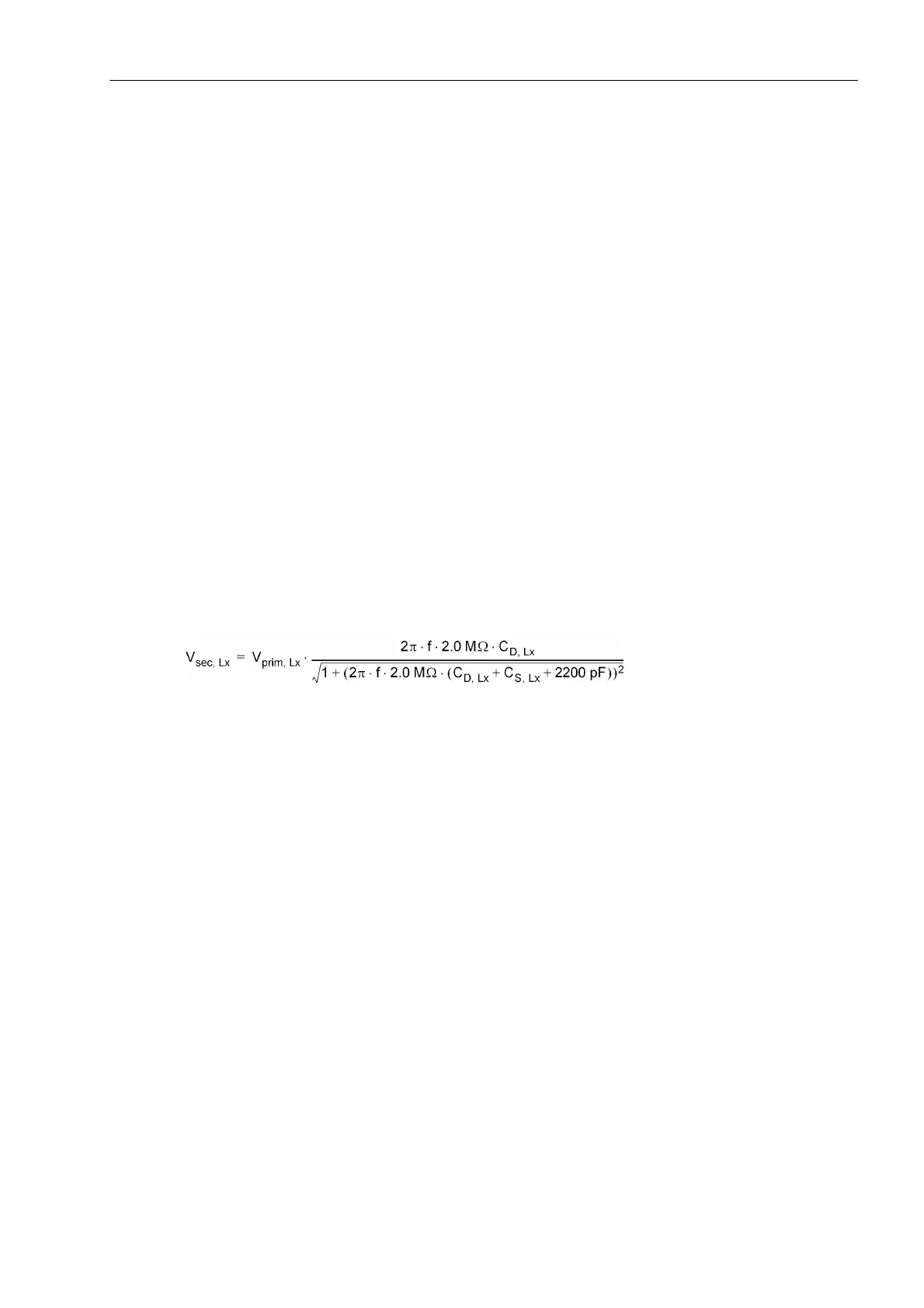
The voltages at the inputs of the protection devices are the result of the primary nominal voltage, the capaci-
tances in the power system and the impedances of the voltage inputs which are taken into account. These volt-
ages can assume different values for three voltage inputs. The voltage V
secondary, x
for phase x can be deter-
mined using the following formula:
with
V
prim, x
Primary voltage of phase x
V
sec, x
Voltage at the voltage input of the protection device
C
D,Lx
Value of the bushing capacitance for phase x
C
S,Lx
Value of the line and stray capacitance for phase x
exec. System frequency (50 Hz or 60 Hz)
The following figure represents the above equation graphically. The frequency is 50 Hz. With a frequency of
60 Hz, the ratio of secondary voltage to primary voltage is about 20 % higher than the values in this example.
The x-axis shows the value of the bushing capacitance. The y-axis shows the resulting ratio o f secondary
voltage to primary voltage. As an additional parameter the value C
S,LX
+ 2200 pF, which is the sum of line ca-
pacitance, stray capacitance and input capacitance, is varied in a range from 2000 pF to 10,000 pF in incre-
ments of 500 pF. Since the input capacitance of 2200 pF can have a tolerance of ±20 %, values higher than
1800 pF are recommended here.
Phase A 241 Volt.trans.A:C1
242 Volt.trans.A:C2
= C
D,A
= C
S,A
+ 2200 pF
Phase B 243 Volt.trans.B:C1
244 Volt.trans.B:C2
= C
D,B
= C
S,B
+ 2200 pF
Phase C 245 Volt.trans.C:C1
246 Volt.trans.C:C2
= C
D,C
= C
S,C
+ 2200 pF

 Loading...


