2 Functions
132
7UT613/63x Manual
C53000-G1176-C160-2
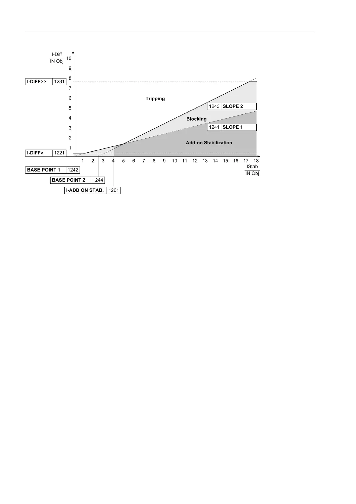
Figure 2-49 Tripping characteristic of the differential protection
The tripping characteristic comprises two further branches. The base point of the first
branch is determined by address 1242 BASE POINT 1 and its slope by address 1241
SLOPE 1. This parameter can only be set with DIGSI under Additional Settings. This
branch covers current-proportional errors. These are mainly errors of the main current
transformers and, in case of power transformers with tap changers, differential cur-
rents which occur due to the transformer regulating range.
The percentage of this differential current in this latter case is equal to the percentage
of the regulating range provided the rated voltage is corrected according to the de-
scription of the 2.1.4 in „Object Data with Transformers“.
The second branch produces a higher restraint in the range of high currents which
may lead to current transformer saturation. Its base point is set at address 1244 BASE
POINT 2 and is referred to the rated object current. The slope is set at address 1243
SLOPE 2. The restraint during current transformer saturation can be influenced by this
parameter branch. A higher gradient results in a higher restraint. This parameter can
only be set with DIGSI at Additional Settings.
Delay Times In special cases it may be advantageous to delay the trip signal of the differential pro-
tection. For this, an additional delay can be set. The delay time1226 T I-DIFF> is
started if an internal fault in the protected object has been detected by the I
DIFF
>-stage
and the trip characteristic. 1236 T I-DIFF>> is the time delay for the tripping stage
I-DIFF>>. This parameter can only be set with DIGSI at Additional Settings. The
dropout time of all stages is determined by the minimum trip time duration of all pro-
tection functions.
All setting times are additional delay times which do not include the operating times
(measuring time, dropout time) of the protective function.
 Loading...


