2.16 Frequency Protection
265
7UT613/63x Manual
C53000-G1176-C160-2
2.16.2 Setting Notes
General The application of frequency protection is only possible in 3-phase protected objects.
Furthermore, it is required that the device is connected to a three-phase voltage trans-
former.
Frequency protection is only in effect and accessible if address 156 was set to
FREQUENCY Prot. Enabledduring configuration of the protection function (section
2.1.3.
Under address 5601 O/U FREQUENCY the frequency protection ON or OFFcan be set.
Furthermore, the command can be blocked if the protective function is enabled
(Block relay).
Pickup Values,
Times
If the frequency protection is used for network splitting or load shedding, the setting
values depend on the system conditions. Normally, the objective is a graded load
shedding that takes the priority of consumers or consumer groups into account.
Other types of application are available in the power station sector. The frequency
values to be set mainly depend, also in these cases, on power system/power station
operator specifications. In this context, frequency decrease protection ensures the
power station's own demand by disconnecting it from the power system on time. The
turbo regulator then regulates the machine set to nominal speed so that the station's
own requirement can be continuously provided with rated frequency.
Generally, turbine-driven generators can be continuously operated down to 95 % of
nominal frequency provided that the apparent power is reduced proportionally. How-
ever, for inductive consumers, the frequency reduction not only means greater current
consumption but also endangers stable operation. Therefore, a short-term frequency
reduction down to approx. 48 Hz (at f
N
= 50 Hz) or 58 Hz (at f
N
= 60 Hz) or 16 Hz (at
f
N
= 16,7 Hz) is permitted.
A frequency increase can, for example, occur due to a load shedding or malfunction-
ing of the speed control (e.g. in an island network). A frequency increase protection,
e.g. as speed control protection can be used here.
The setting ranges of the frequency stages depend on the set rated frequency. The
three underfrequency stages are set under addresses
By means of setting an underfrequency stage to 0, it can be deactivated. If the over-
frequency stage is not required, set it to ∞.
The delay times can be set under addresses 5641 T f<, 5642 T f<<, 5643 T f<<<
and 5644 T f>. Hereby, a grading of frequency stages can be achieved or the re-
quired switching operations in the power station sector can be triggered. The set times
are pure additional delay times that do not include the operating times (measuring
time, drop-out time) of the protective function. If a delay time is set to ∞, this does not
result in a trip, but the pickup will be indicated.
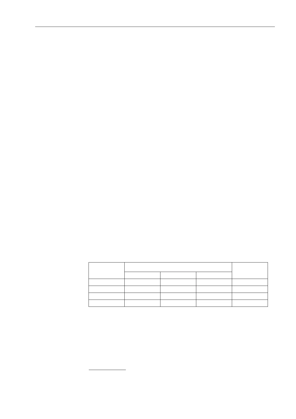
Setting example:
Level Address at f
N
=
Parameter
name
50 Hz 60 Hz 16.7 Hz
f<Stage 5611 5621 5631 f<
f<<Stage 5612 5622 5632 f<<
f<<<Stage 5613 5623 5633 f<<<
f>Stage 5614 5624 5634 f>
 Loading...


