4.9 Thermal Overload
465
7UT613/63x Manual
C53000-G1176-C160-2
4.9 Thermal Overload
Setting Ranges
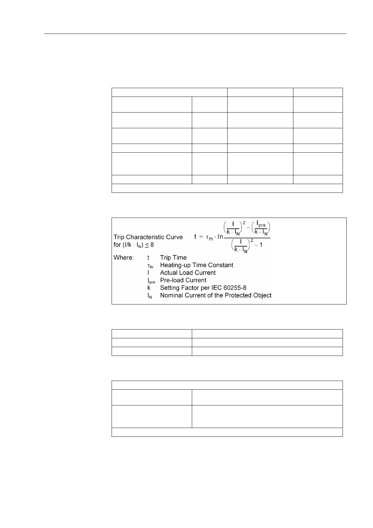
Trip Curve
Dropout to Pickup Ratios
Tolerances
Factor k according to IEC 60255-8 0.10 to 4.00 Steps 0.01
Time constant τ 1.0 min to 999.9 min Increments
0.1 min
Cooling down factor at motor
stand-still
K
τ
-factor 1.0 to 10.0 Steps 0.1
Thermal alarm stage Θ
Alarm
/Θ
Trip
50% to 100% referred to
trip temperature rise
Steps 1 %
Current alarm stage I
Alarm
0.10 to 4.00 A
1)
Steps 0.01 A
Start-up recognition I
motor startup
0.60 to 10.00 A
1)
or ∞ (no start-up recogni-
tion)
Steps 0.01 A
Emergency start run-on time T
Run-on
10 s to 15000 s Steps 1 s
1)
Secondary values based on I
N
= 1 A; for I
N
= 5 A the currents must be multiplied by 5.
Θ/Θ
OFF
Dropout with Θ
Alarm
Θ/Θ
Alarm
approx. 0.99
I/I
Alarm
approx. 0.97
For one 3-phase measuring location
relating to k · I
N
3 % or 10 mA
1)
;
class 3% according to IEC 60255-8
Referring to tripping time 3 % or 1.2 s at f
N
= 50 / 60 Hz
5 % or 1.2 s at f
N
= 16.7 Hz
for I/(k·I
N
) > 1.25
1)
Secondary values based on I
N
= 1 A; for I
N
= 5 A the currents must be multiplied by 5.
 Loading...


