4 Technical Data
480
7UT613/63x Manual
C53000-G1176-C160-2
4.19 Monitoring Functions
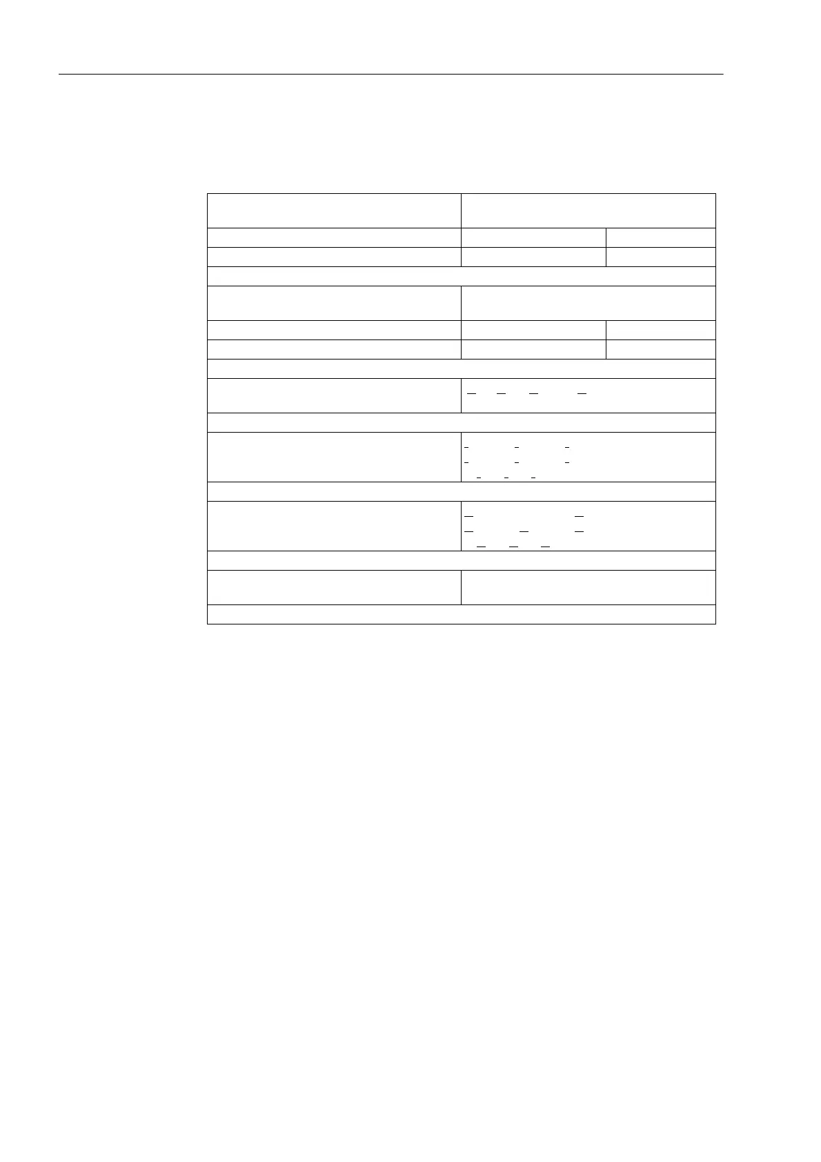
Measured Quantities
Current symmetry
(for each side)
|I
min
|/|I
max
| < BAL. FACT. I M1
provided that I
max
/I
N
> BAL. I LIMIT M1/I
N
BAL.FAC. I 0.10 to 0.90 Steps 0.01
BAL. I LIMIT 0.10 A to 1.00 A
1)
Steps 0.01 A
Voltage balance
(if voltages applied)
|U
min
|/|U
max
| < BAL. FACTOR U
provided that |U
max
| > BALANCE U-LIMIT
BAL.FACTOR. U 0.58 to 0.90 Increments 0.01
BALANCE I LIMIT 10 V to 100 V Increments 1 V
Voltage sum
(if voltages applied)
|U
L1
+ U
L2
+ U
L3
– k
U
U
en
| > 25 V
Current phase sequence I
L1
leads I
L2
leads I
L3
if clockwise
I
L1
leads I
L3
leads I
L2
if counter-clockwise
if |I
L1
|, |I
L2
|, |I
L3
| > 0.5 I
N
Voltage phase sequence
(if voltages applied)
U
L1
leads U
L2
leads U
L3
if clockwise
U
L1
leads U
L3
leads U
L2
if counter-clockwise
if |U
L1
|, |U
L2
|, |U
L3
| > 40 V/√ 3
Broken wire unexpected instantaneous current value and
current interruption or missing zero crossing
1)
Secondary values based on I
N
= 1 A; for I
N
= 5 A they must be multiplied with 5.
 Loading...


