2 Functions
212
7UT613/63x Manual
C53000-G1176-C160-2
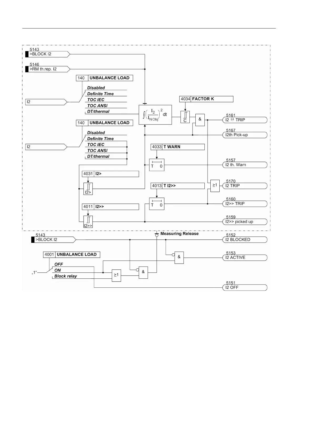
Figure 2-96 Logic diagram of the asymmetrical load protection - illustrated for the thermal stage with I>> stage (simpli-
fied)
2.8.2 Setting Notes
General Unbalanced load protection only makes sense with three-phase protected objects. For
PROT. OBJECT = 1ph Busbar or 1 phase transf. (address 105) the following
settings are not available.
The characteristic type has been determined during configuration of the functional
scope under address 140 UNBALANCE LOAD (see section 2.1.3.1). Only the settings
for the characteristic selected can be performed here. The inverse time curves I
2
>>
and I
2
> are available in all cases.
 Loading...


