2.8 Unbalanced Load Protection
211
7UT613/63x Manual
C53000-G1176-C160-2
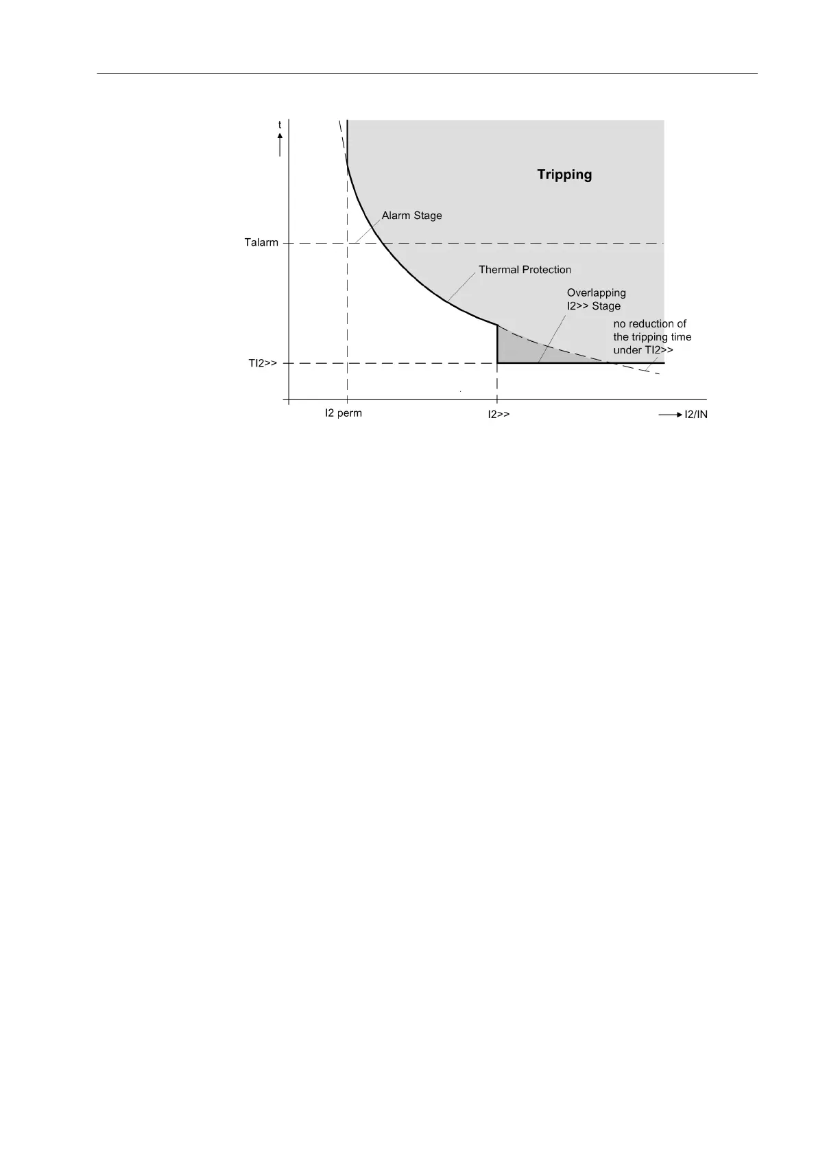
Figure 2-95 Resulting characteristic of the thermal asymmetrical load protection
Logic Figure 2-96 shows the logic diagram for the breaker failure protection with the thermal
stage and the definite time I
2
>> stage. The I
2
> stage is not represented. It is available
in this operating mode, but is generally not required because an own warning level is
available. The protection may be blocked via a binary input. That way, pickups and
time stages are reset. The content of the thermal replica can be emptied via the binary
input „>SLS RES th.repl“ and „>ULP Block“.
When leaving the work area of the negative sequence protection (all phase currents
under the minimum current setting „I REST“ for the concerned measuring location or
side or at least one phase current is greater than 4 · I
N
) .
 Loading...


