2 Functions
204
7UT613/63x Manual
C53000-G1176-C160-2
The required short-term power of the resistor is derived from the knee-point voltage
and the resistance:
As this power only appears during earth faults for a short period of time, the rated
power can be smaller by approx. factor 5.
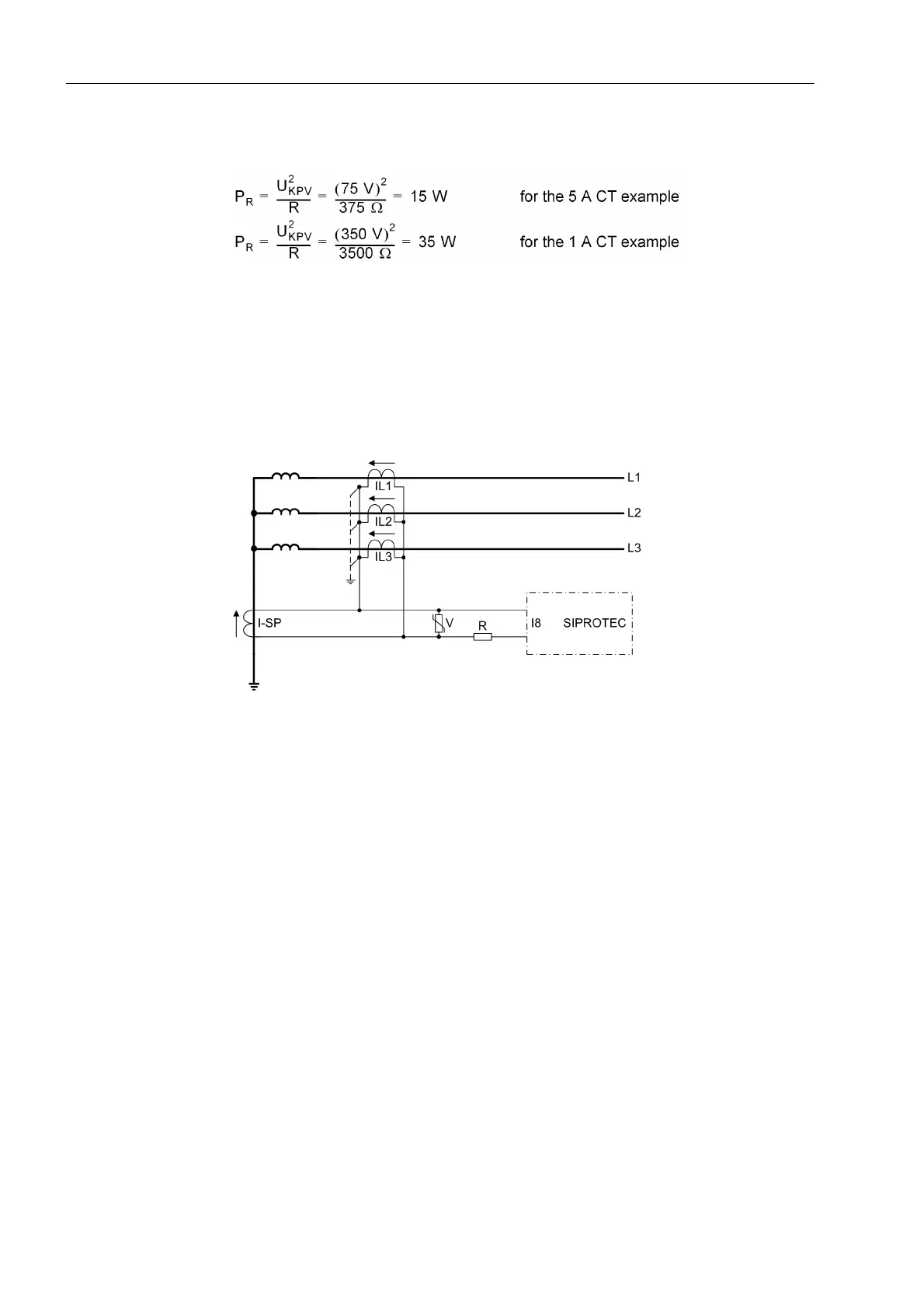
The varistor (see figure below) must be dimensioned in such manner that it remains
high-ohmic up to the knee-point voltage, e.g.
approx. 100 V for 5-A CT,
approx. 500 V for 1-A CT.
Figure 2-91 Connection scheme for restricted earth fault protection according to the high-im-
pedance principle
The pickup value (0.1 A or 0.05 A in the example) is set in address 2706 1Phase I>.
The I>> stage is not required (address 2703 1Phase I>> = ∞).
The trip command can be delayed under address 2707 T 1Phase I>. This time
delay is usually set to 0.
If a higher number of current transformers is connected in parallel, e.g. when using as
busbar protection with several feeders, the magnetising currents of the transformers
connected in parallel cannot be neglected anymore. In this case, the sum total of the
magnetising currents at half knee-point voltage (corresponding to the setting value)
has to be established. These magnetising currents reduce the current through the re-
sistor R. The actual pickup value thus increases accordingly.
Use as Tank
Leakage Protection
If the single-phase time overcurrent protection is used as tank leakage protection, only
the pickup value for the respective 1-phase current input is set on 7UT613/63x.
The tank leakage protection is a highly sensitive overcurrent protection which detects
the leakage current between the isolated transformer tank and earth. Its sensitivity is
set in address 2706 1Phase I>. Stage I>> is not used (address 2703 1Phase I>>
= ∞).
The trip command can be delayed in address 2707 T 1Phase I>. Normally, this
delay time is set to 0.
 Loading...


