2.19 Monitoring Functions
281
7UT613/63x Manual
C53000-G1176-C160-2
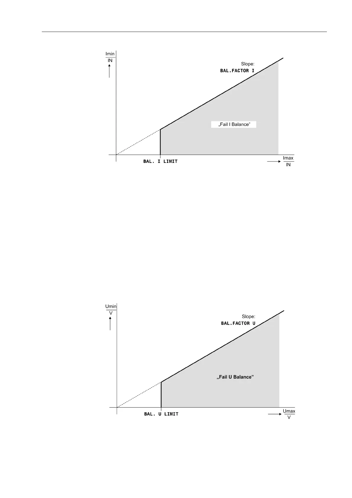
Figure 2-114 Current Symmetry Monitoring
Voltage Symmetry In healthy network operation it can be expected that the voltages are nearly balanced.
If measured voltages are connected to the device, this symmetry is checked in the
device by magnitude comparison. To do this, the phase-to-earth voltages are mea-
sured. The lowest phase-to-earth voltage is set in relation to the highest. An imbalance
is detected when
|U
min
|/|U
max
| < BAL. FACTOR U as long as |U
max
| > BALANCE U-LIMIT
TherebyU
max
is the largest of the three phase-to-phase voltages and U
min
the smallest.
The symmetry factor BAL. FACTOR U is the measure for the asymmetry of the con-
ductor voltages; the limit value BALANCE U-LIMIT is the lower limit of the operating
range of this monitoring (see Figure Voltage Symmetry Monitoring). Both parameters
can be set. The dropout ratio is about 95 %.
This malfunction is reported as „Fail U balance“.
Figure 2-115 Voltage Symmetry Monitoring

 Loading...


