2 Functions
304
7UT613/63x Manual
C53000-G1176-C160-2
A correct display of primary and percentage values requires the complete and correct
entry of the topology of the protected object and its rated values, as well as of the
transformer ratings.
For the measuring locations
the primary and secondary measured values as per Table
2-12 are issued. Depending on the device’s order number, connection type, topology
and protection functions configured, only a part of the magnitudes listed there is avail-
able. For single-phase transformers all phase sizes are missing L2.
The powers S, P, Q are calculated from the measuring location to which the voltage
transformers are assigned. If the voltage transformers are assigned to a side of the
main protected object, the current sum applies, if the side has two or more measuring
locations. With single-phase busbar protection, power calculation is not possible.
The definition of the signs is normally that the power flowing into the protective object
is considered as positive: Active components and inductive reactive components in
the direction of the protective object are positive. The same applies for the power
factor cos ϕ. It is occasionally desired to define the power draw from the protected
object (e.g. as seen from the user side of the transformer) positively. Using parameter
address 1107 P,Q sign the signs for these components can be inverted.
For devices without voltage measuring inputs a voltage and apparent power can be
issued, if the voltage is connected to a one-phase current measuring input via an ex-
ternal series resistor. Via a user-configurable CFC logic (CFC block „Life_Zero“) the
current proportional to the voltage can be measured and indicated as voltage „U
meas
“.
For more details on the procedure refer to the CFC manual.
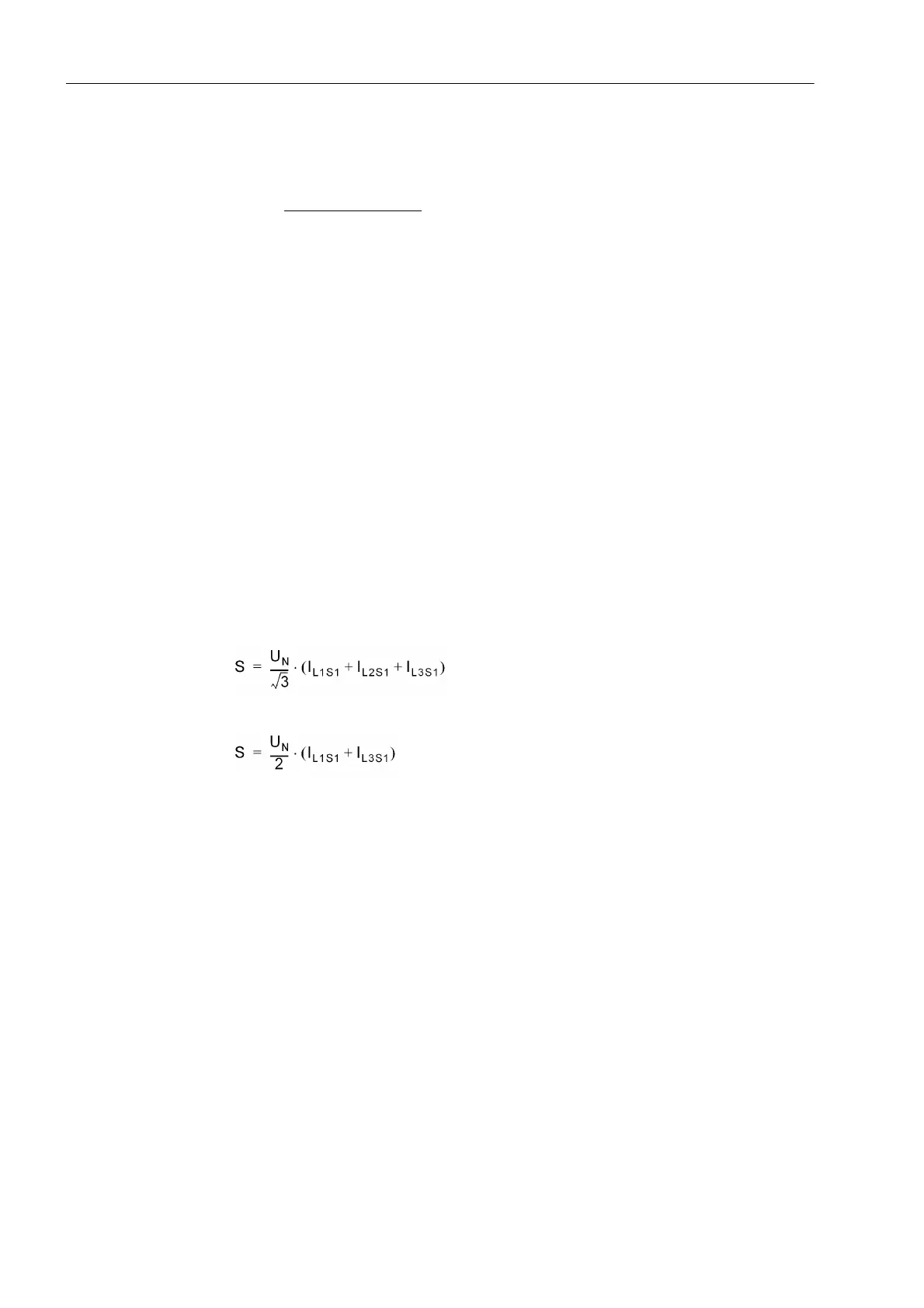
The apparent power „S“ is not a measured value, but a value calculated from the rated
voltage of the protected object which is set and the actually flowing currents of side 1:
so
for three-phase application or
for single-phase transformers. If, however, the voltage measurement described in the
previous paragraph is applied, this voltage measurement is used to calculate the ap-
parent power with the currents of side 1. The apparent power is given as magnitude;
it does not contain direction information.

 Loading...


