3 Mounting and Commissioning
348
7UT613/63x Manual
C53000-G1176-C160-2
When performing work on plug connectors, proceed as follows:
• Disconnect the ribbon-cable between the front cover and the C–CPU-2 (1) board.
To disconnect the cable, push up the top latch of the plug connector and push down
the bottom latch of the plug connector. Carefully set aside the front cover.
• Disconnect the ribbon cables between the C-CPU-2 (1) board and the I/O boards
(2 to 4, depending on version).
• Remove the boards and set them on the grounded mat to protect them from ESD
damage. In the case of the device variant for panel surface mounting, please be
aware of the fact that a certain amount of force is required in order to remove the
C-CPU-2 module due to the existing plug connectors.
• Check the jumpers in accordance with the figures and information provided below,
and as the case may be change or remove them.
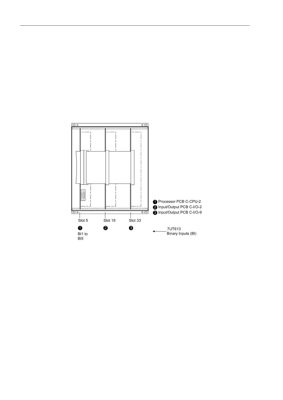
Module Arrange-
ment 7UT613/63x
Figure 3-3 Front view with housing size
1
/
2
after removal of the front panel (simplified and
scaled down)
 Loading...


